Installing fuselage components, Spinner assembly – Carl Goldberg GPMA1956 Eagle 2 ARF User Manual
Page 15
15
CAUTION: The spinner, propeller, and engine, if improperly
installed, or if misused, may result in serious injury to you
or to others. Follow the spinner assembly instructions, and
other instructions and warnings elsewhere in this book,
carefully.
General Precautions:
·
Never use a spinner where the cut-out is too small
for the propeller you are using.
·
Follow the engine and prop mounting instructions.
·
Inspect frequently, and discard any prop with nicks,
scratches, splits, cracks, or any other signs of damage.
Never repair a prop!
·
Inspect for loosening and retighten using a prop
wrench.
·
Make sure you and any spectators are not in the
plane of rotation of a prop.
·
Protect you eyes with safety glasses.
·
Get expert advice from your dealer or equipment
manufacturer, if you have any questions or concerns
regarding the spinner, engine, or propeller.
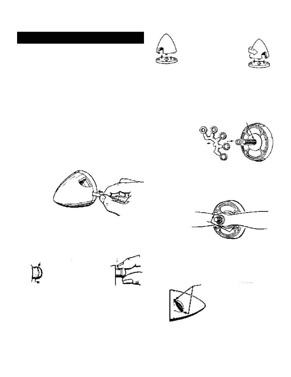
1.
Open the spinner by carefully pushing a
small screwdriver (one that does not exceed the width of
the slot) straight into all four slots. DON'T TWIST! For
safety, hold the screwdriver close to the tip.
2.
Examine the Retaining Pins closely for
possible tiny threads and remove.
Rub fingers around the Retaining Pins, to
give them a little lubrication.
3.
"Work in" the spinner by assembling and
disassembling three or four times, rotating the pins each
time before snapping the spinner to the backplate. The
spinner will be quite stiff, at first. You may also boil it in a
pan of water for 20 minutes to rehydrate the nylon and
make it more workable.
4.
Place the backplate on the engine. It
should fit snuggly. If it does not, add one of the
bushings provided, using a drop of glue to secure it, if nec-
essary.
5.
Set the prop against the locator pins and
hold while tightening the nut. The prop may turn away
from the pins, as you tighten. If this happens, secure the
prop with a small drop of CA glue. If you are not satisfied
with the prop-to-spinner match-up using the locator pins,
rotate the prop 90° and adjust prop as desired.
6.
Large cutouts have been molded into the
spinner for propeller clearance. Make sure the prop you
have selected has clearance all around.
INSTALLING FUSELAGE COMPONENTS
SPINNER ASSEMBLY
Push Stright Into
Slots
Finger Lube Pins
Retaining
Pin
Thread
Repeat This Sequence
Bushings Furnished
With 2” to 3” Spinners
only
Select
Best
Bushing
Bushing
Locating Pins
Clearance All Around