Dc power supply replacement – AERCO Electronic Controls System (ECS) User Manual
Page 64
Electronic Control System (ECS) and Type CXT-E Valve
9. RECOMMENDED SPARE PARTS
Page 64 of 82
AERCO International, Inc. • 100 Oritani Dr. • Blauvelt, New York 10913 • Phone: 800-526-0288
VD2: 02/28/14
OMM-0003_0D
AC-105
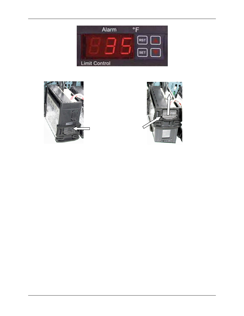
Figure 8-8a. Over-Temperature Switch & Temperature Indicator
Figure 8-8b. Over-Temperature Switch & Temperature Indicator Installation
5) If the replaced unit is an Over-Temperature Switch, set the desired over-temperature alarm
limit using the Adjustment procedures in Section 3. No adjustments are required following
replacement of the Boiler Water IN or Boiler Water OUT Temperature Indicator on water-to-
water heaters.
6) Following adjustment (if necessary), raise and secure the swing-down panel. Close and
secure the Control Box door. If adjustments or replacements have been made, refer to the
Adjustment procedures in Section 3 and repeat as necessary.
8.3.5 DC Power Supply Replacement
The DC Power Supply is mounted on the left interior wall of the Control Box (see Figure 8-9,
View A - A). Replacement is accomplished as follows:
1) Open the Control Box door and loosen the captive screw on the recessed panel behind the
door.
2) Open the swing-down panel and locate the DC Power Supply on the left interior wall of the
Control Box (Figure 8-9, View A - A).
3) Disconnect the AC input power connector near the bottom of the Power Supply and the DC
output connector near the top.
4) Remove the four hex standoffs and lock washers securing the DC Power Supply to the
studs on the interior side wall of the Control Box. Completely remove the DC Power Supply
from the Control Box.
5) Replacement is accomplished by simply reversing the previous steps.
To uninstall
push tab to release clip
retainer. Slide clip back
and off. Remove
assembly through front
panel.