Setpoint temperature adjustment, Op 1 op 2 sp2 rem – AERCO Electronic Controls System (ECS) User Manual
Page 28
Electronic Control System (ECS) and Type CXT-E Valve
3. ADJUSTMENT
Page 28 of 82
AERCO International, Inc. • 100 Oritani Dr. • Blauvelt, New York 10913 • Phone: 800-526-0288
VD2: 02/28/14
OMM-0003_0D
AC-105
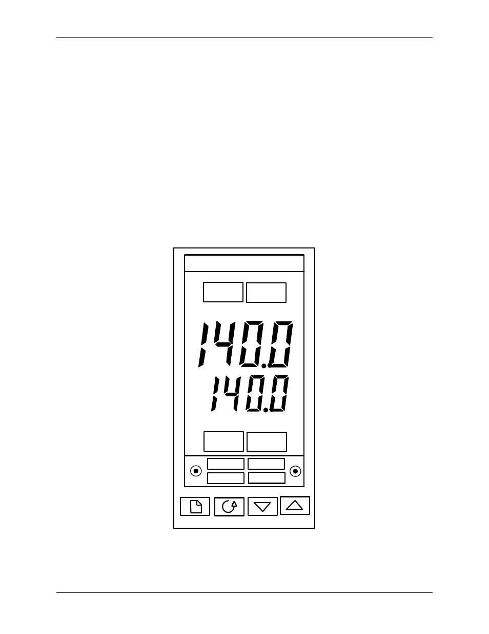
3.3.1 Setpoint Temperature Adjustment
The setpoint temperature is adjusted using the controls and displays provided on the
Temperature Controller. These controls and displays are illustrated and described in Figure 3-3
and Table 3-1. If necessary, setpoint temperature adjustment is accomplished as follows:
1) With the Control Box door open, set the ON/OFF POWER switch on the right side to the ON
position. The Temperature Controller will initiate a self-test for approximately 3 seconds.
Following the self-test, the top display will show the current outlet water temperature of the
Heater and the lower display will show the current setpoint temperature stored in memory
(default = 140°F).
2) Ensure that the Temperature Controller is set to the AUTO (automatic) mode and the AUTO
indicator is lit. If the MAN indicator is lit, press the AUTO/MAN button to toggle the mode
setting. Indicator OP1 will be lit if the process is calling for heat.
3) If the lower display does not show the d
esired setpoint temperature, press the ▲ or ▼ arrow
button to change the display to the desired value.
4)
Two seconds after the ▲ or ▼ arrow button is released, the display will blink to indicate that
the Temperature Controller has accepted and stored the displayed value.
AUTO
RUN
MAN
HOLD
OP 1
OP 2
SP2
REM
2408
Figure 3-3. Temperature Controller