AERCO Electronic Controls System (ECS) User Manual
Page 60
Electronic Control System (ECS) and Type CXT-E Valve
9. RECOMMENDED SPARE PARTS
Page 60 of 82
AERCO International, Inc. • 100 Oritani Dr. • Blauvelt, New York 10913 • Phone: 800-526-0288
VD2: 02/28/14
OMM-0003_0D
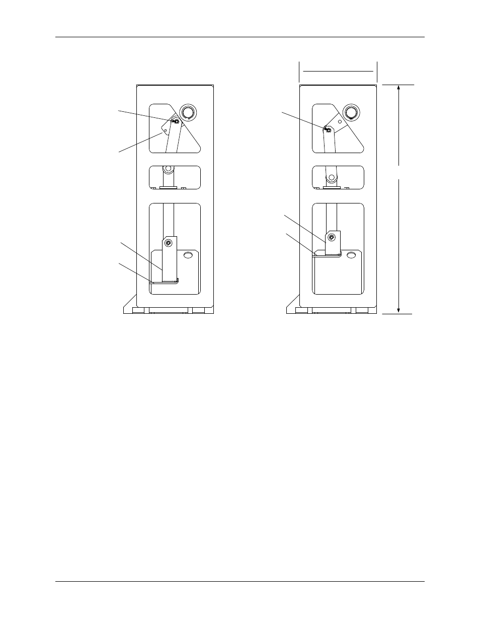
AC-105
ADAPTER
PART NO. 24038-1
(FOR 1 TO 3 IN. VALVES)
USE THIS PIN
LOCATION FOR
4 IN. VALVES
USE THIS PIN
LOCATION FOR
1 - 2 IN. VALVES
ADAPTER
PART NO. 24038-2
(FOR 4 IN. VALVE ONLY)
13 - 3/8 IN.
4–1/2 IN. x
1-15/16 IN. WIDE
USE THIS PIN
LOCATION FOR
2 -1/2 & 3 IN.
VALVES
INDICATOR
PLATE
INDICATOR
PLATE
Figure 8-6. Linkage Assemblies
If necessary, the Linkage Assembly is removed and replaced as follows:
1) Remove the Actuator using steps CM45 through CM48 in the previous paragraph titled
ACTUATOR REPLACEMENT.
2) Next, refer to Figure 8-1 (1” to 2” Valves or 8-2 (2 ½” to 4” Valves) to locate item numbers
shown in parentheses in the following steps.
3) Loosen the Hex Nuts (17) under the Indicator Plate (Figure 8-1 or 8-2) approximately a half
turn clockwise.
4) Disconnect the Linkage Adapter from the Valve Shaft (16) by turning the Shaft clockwise
(as viewed from above). If the Valve Shaft cannot be turned by hand, use an open-end
wrench to turn the “double-nuts” on the Shaft until it disengages the Linkage Adapter
threads.
5) Remove the Indicator Plate from the Valve Shaft (16).
6) Remove the two Cap Screws (19) securing the Linkage Assembly (26) to the Valve Top
(21).
7) Remove the Linkage Assembly (26) from the Valve Top. Also, remove the Gasket (29)
which will be replaced.