AERCO Electronic Controls System (ECS) User Manual
Page 63
Electronic Control System (ECS) and Type CXT-E Valve
VD2: 02/28/14 AERCO International, Inc. • 100 Oritani Dr. • Blauvelt, New York 10913 • Phone: 800-526-0288
Page 63 of 82
AC-105
OMM-0003_0D
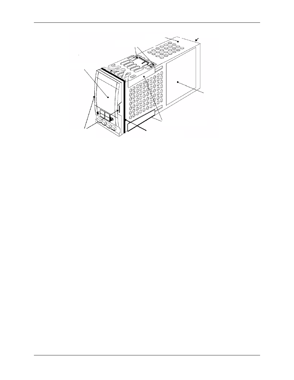
TERMINAL COVERS
SLEEVE
LABEL
PANEL RETAINING
CLIPS
PANEL SEALING
GASKET
LATCHING
EARS
DISPLAY
RATCHETS
Figure 8-7. Temperature Controller Installation
4) Close and secure Control Box front door.
8.3.4 Over-Temperature Switch and Temperature Indicator Replacement
The Over-Temperature Switch and Temperature Indicators are actually identical devices,
however they perform different functions. One Over-Temperature Switch is provided in each
Control Box for both Steam-to-Water and Water-to-Water applications. As the name implies, the
Over-Temperature Switch, performs a switching function and generates an alarm when the
preset temperature limit is exceeded. However, the Temperature Indicators, used only with
Water-to-Water Heat Exchangers, are Indicator-Only devices and are not wired to perform any
switching functions. The locations of the Over-Temperature Switch and Temperature Indicators
for Steam-to-Water and Water-to-Water applications are shown in Figure 1-3. Removal and
replacement for each device are performed using the following identical steps:
1) Open the Control Box door to locate the Temperature Switch/Indicator assembly.
2) Loosen the captive screw on upper part of recessed panel behind the door and open the
swing-down panel to access the terminal wiring connections and retaining clips of the
Temperature Switch/Indicator assembly (Figure 8-8a).
3) Loosen the terminal wiring connection screws on the rear of the Temperature
Switch/Indicator assembly and disconnect the wires.
NOTE:
The Type J Thermocouples are wired with the Red lead Negative (-)
and the White lead Positive (+).
4) To remove the Temperature Switch/Indicator assembly, push in tab of each of two side
retaining clips (Figure 8-8b), slide toward rear and remove.