AERCO Electronic Controls System (ECS) User Manual
Page 16
Electronic Control System (ECS) and Type CXT-E Valve
2. INSTALLATION
Page 16 of 82
AERCO International, Inc. • 100 Oritani Dr. • Blauvelt, New York 10913 • Phone: 800-526-0288
VD2: 02/28/14
OMM-0003_0D
AC-105
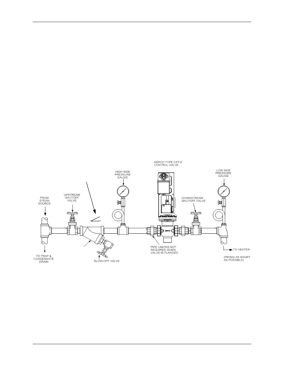
7) If the Valve is controlling steam, ensure that the steam line is properly trapped to prevent
accumulation of condensate ahead of the Valve.
8) Install Shutoff Valves (metal-seated, gate-type) upstream and downstream of the Control
Valve to permit removal from the line for maintenance.
9) Pressure gauges should be installed on both sides of the Control Valve as shown in Figure
2-1 (steam) or Figure 2-2 (hot water).
10) The gauge on the high pressure side of the Valve is for adjustment and maintenance
purposes. The gauge on the low pressure side is to ensure that the correct pressure is
being introduced to the Control Valve. For either steam or water flow, the low side gauge
denotes the pressure of the fluid in the line which may create a hazardous condition.
11) A temperature gauge should be installed in the high pressure side of a hot (boiler) water
line as shown in Figure 2-2.
12) Install the Control Valve with the arrow on the Valve Body pointing in the direction of flow.
13) After the Control Valve has been installed in the steam or hot water line, ensure that all
piping connections are secure and leak tight.
14) This completes the installation procedures for the Control Valve. Proceed to the next
paragraph titled ELECTRONIC CONTROL SYSTEM INSTALLATION.
Figure 2-1. Recommended Control Valve, CXT-E Installation For Steam Flow
STRAINER WITH 0.020
MEST STAINLESS
STEEL BASKET,
SHOWN ROTATED
DOWN 90 DEGREES
FOR CLARITY
PIPING PITCH DIRECTION
1 TO 40 RATIO MINIMUM