Installation, 1 introduction, 2 electronic control valve type cxt-e installation – AERCO Electronic Controls System (ECS) User Manual
Page 15: Introduction, Electronic, Control, Valve, Type, Cxt-e
Electronic Control System (ECS) and Type CXT-E Valve
2. INSTALLATION
VD2: 02/28/14 AERCO International, Inc. • 100 Oritani Dr. • Blauvelt, New York 10913 • Phone: 800-526-0288
Page 15 of 82
AC-105
OMM-0003_0D
2. INSTALLATION
2.1 INTRODUCTION
Normally, the Electronic Control System (ECS) is shipped already installed on the Packaged
Water Heater. However, the Control Valve, Type CXT-E is packed separately. For smaller size
Valves (1” to 2”), the packaged Valve is attached to the base of the shipping crate. For larger
size Valves (2 ½” to 4”), the packaged Valve may be shipped separately due to space
limitations within the Heater shipping crate. Therefore, the installation procedures consist
basically of:
• Installing the Electronic Control Valve, Type CXT-E and associated steam or hot (boiler)
water piping and components.
• Connecting external power to the ECS Control Box
• Connecting and checking electrical connections to the CXT-E Actuator and other ECS
components
IMPORTANT NOTE!
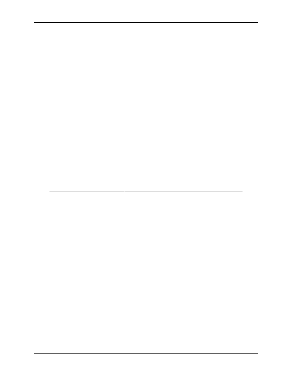
For Water-to-Water Double-Wall (WWDW) heaters equipped with the
ECS, the following minimum recirculation flow must be provided to
achieve ±4°F temperature control under normal diversified domestic
load conditions:
Double-Wall Model
Minimum System Recirculation
WWDW24
10 gpm
WWDW45
15 gpm
WWDW68
20 gpm
2.2 ELECTRONIC CONTROL VALVE TYPE CXT-E INSTALLATION
The following procedures apply to all sizes of AERCO Electronic Control Valves Type CXT-E
ranging from 1 inch to 4 inches. In addition, the following steps can be used for both steam and
hot (boiler) water flow systems. Proceed as follows:
1) Refer to Figure 1-3 for dimensions of the Control Valve furnished with the Packaged Water
Heater.
2) Next, refer to the recommended installation drawing in Figure 2-1 for steam flow, or Figure
2-2 for hot (boiler) water flow.
3) Install the Control Valve with the Actuator Linkage in the vertical, upright position as shown
in Figure 2-1 or 2-2.
4) For maintenance purposes, unions are required with threaded ends to simplify removal
from the steam or hot boiler water line.
5) Blow out all pipe lines to clear them of dirt chips, scale or other foreign matter which could
adversely affect Valve operation when in service.
6) Install an in-line strainer upstream of the Valve as shown in Figure 2-1 (steam) or Figure 2-
2 (hot boiler water). This will protect against foreign matter reaching the Valve during
service operation.