Flow sensor – AERCO Electronic Controls System (ECS) User Manual
Page 37
Electronic Control System (ECS) and Type CXT-E Valve
6. ROUTINE MAINTENANCE
VD2: 02/28/14 AERCO International, Inc. • 100 Oritani Dr. • Blauvelt, New York 10913 • Phone: 800-526-0288
Page 37 of 82
AC-105
OMM-0003_0D
6.3.4 Flow Sensor:
The Flow Sensor is installed between the Heater water inlet line and the Heater drain (refer to
Figures 1-1 & 5-1). Check this sensor for evidence of blockage or scale build-up as follows:
1) Disconnect the electrical connector from the Flow Sensor.
2) Loosen the fittings at the Sensor inlet and outlet connections and completely remove the
Sensor. To ease removal, loosen the strain relief on the flow sensor cable. This creates
clearance for the removal of the fitting on the meter body.
3) Inspect the Sensor inlet and outlet for blockage and clean as necessary.
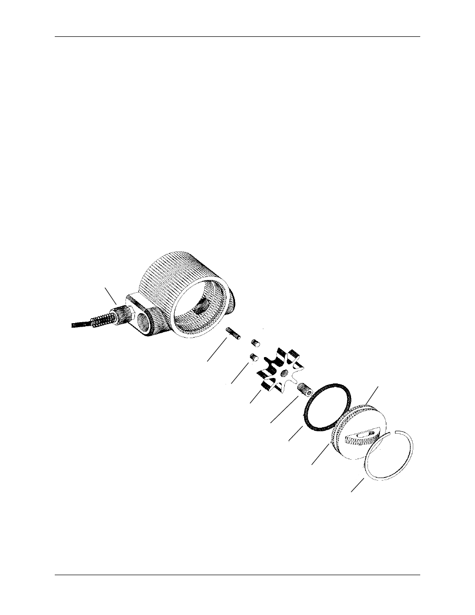
4) Refer to Figure 6-2 and disassemble the Flow Sensor as follows:
a) Remove the internal snap-ring.
b) Remove the clear polycarbonate window and O-ring.
c) Remove the turbine paddle wheel.
d) Clean all foreign matter from the Flow Sensor. If replacement parts are needed, order
the appropriate Flow Sensor Rebuild Kit (see Table 9-2) from your local AERCO Sales
Representative.
TURBINE SHAFT
MAGNETS (2)
TURBINE PADDLE WHEEL
PADDLE WHEEL INSERT
O-RING
O-RING
GROOVE
CLEAR POLYCARBONATE
WINDOW
SNAP RING
STRAIN
RELIEF
Figure 6-2. Flow Sensor, Part No. 64006 – Exploded View