Over-temperature alarm limit adjustment – AERCO Electronic Controls System (ECS) User Manual
Page 29
Electronic Control System (ECS) and Type CXT-E Valve
3. ADJUSTMENT
VD2: 02/28/14 AERCO International, Inc. • 100 Oritani Dr. • Blauvelt, New York 10913 • Phone: 800-526-0288
Page 29 of 82
AC-105
OMM-0003_0D
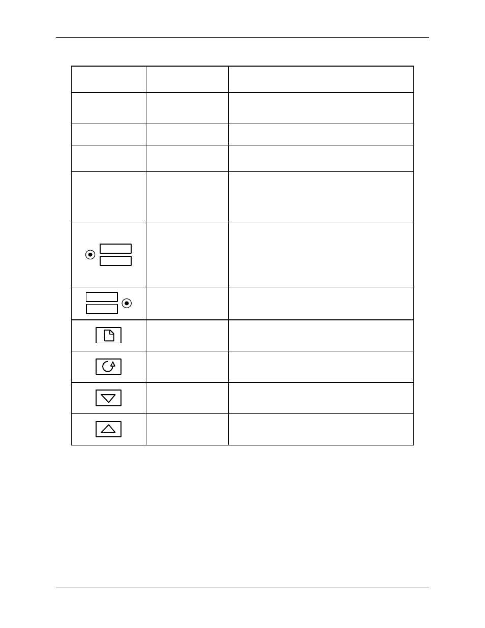
Table 3-1. Temperature Controller Operating Controls, Indicators & Displays
CONTROL or
INDICATOR
MEANING
FUNCTION
OP1
Output 1 Indicator
OP1 lights when a 4 to 20 mA signal is being
supplied to the ECS Valve Actuator
OP2
Output 2 Indicator
Not used for the ECS application
SP2
Setpoint 2
Indicator
Not used for the ECS application
REM
Remote Setpoint
Indicator
REM lights when the ECS is set up to be
controlled by a Remote (Modbus) signal.
REM will also flash when Modbus
communication is active.
AUTO
MAN
Auto/Manual
Button and
Indicators
When button is pressed, the Controller is
toggled between the automatic (AUTO) and
manual (MAN) modes.
AUTO lights when in the automatic mode.
MAN lights when in the manual mode.
RUN
HOLD
Run/Hold Button
and Indicators
Not used for ECS application
Page Button
Press Page button to select a new list of
parameters
Scroll Button
Press Scroll button to select a new parameter
in a list
Down Button
Press to decrease the value shown in the
lower display
Up Button
Press to increase the value shown in the
lower display
3.3.2 Over-Temperature Alarm Limit Adjustment
The over-temperature alarm limit setting is adjusted using the controls and display on the Over-
Temperature Switch. The controls and display are illustrated and described in Figure 3-4 and
Table 3-2. If necessary, over-temperature alarm limit adjustment is accomplished as follows:
1) With the Control Box door open, set the ON/OFF POWER switch to the ON position.
2) Press the SET button on the Over-Temperature Switch. SP will appear in the display.
3) Press the SET button again. The current over-temperature limit value stored in memory will
be displayed (default = 160°F).