A&D Weighing SV-100H User Manual
Page 14
12
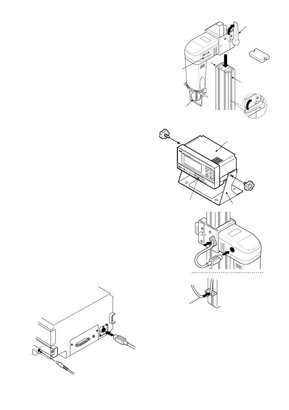
Connection cable
from the display unit
(Connect as shown)
Main unit
Guide channel
Serial number
Lever
Cap
Handle the sensor
plates with care.
5 Raise the lever and install the sensor unit along
the guide channels of the supporting post’s
sides.
At an appropriate height, secure the sensor unit
to the supporting post by lowering the lever.
6 Confirm that the stand’s mounting holes and the
display’s mounting holes match up. Secure both
sides of the display with the knobs.
7 Connect the display unit to the main unit using the
connection cable.
8 Insert the AC adapter plug into the AC
adapter jack located on the rear side of the
display unit. Insert the other end of the AC
adapter plug into an electrical outlet.
Serial number
Knob for securing
the display
Stand
Display
Knob for
securing
the display
AC adapter cable
Display unit
rear side
Connection cable
from the main unit
(Connect as shown)
Note:
• Confirm that the adapter type is correct for
the local voltage and power receptacle type.
• The main unit and the display unit have been
adjusted in pairs. For accurate viscosity
measurement, before use, confirm that the
main unit and the display unit have the same
serial number.