Factory default positions are shown – KEYENCE DL-RB1A User Manual
Page 9
7
1-1
Before Using the Unit
In
tro
du
ct
ion
1
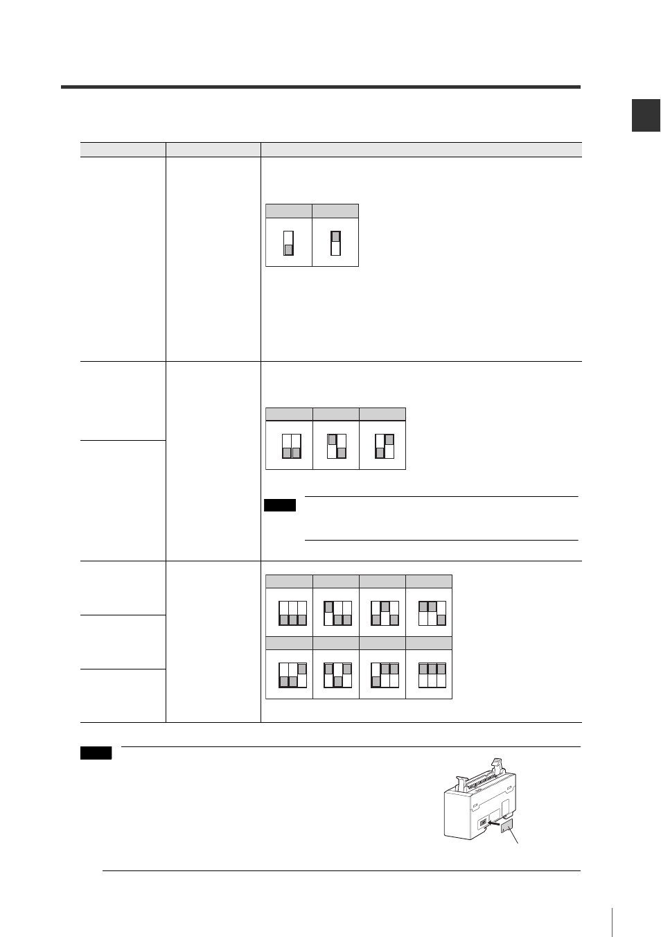
(1) Advanced setting switches
You can use different ON/OFF combinations to configure the output settings.
• Make sure you cycle the power to the unit after modifying
the settings. The modifications are not applied to the unit
until it is powered down and power has been reapplied.
• Place the switch protection sticker supplied with the unit
over the switches after you modify the settings.
Switch No.
Setting item
Combination
1
Output logic
Setting enabled only for BCD output (Pin Nos. 6 to 29) and
BCD polarity code output (Pin No. 30).
* Factory default positions are shown.
Negative logic: The bit for each BCD output will be 1 when the
BCD output (Pin Nos. 6 to 30) is on.
Positive logic: The bit for each BCD output will be 1 when the
BCD output (Pin Nos. 6 to 30) is off.
2
BCD data
output method
Set the method for handling all outputs except for the alarm
output (Pin Nos. 6 to 31).
* Factory default positions are shown.
Do not use combinations other than those shown above for
switch numbers 2 and 3.
3
4
BCD output update
cycle time in the
TIMER mode
* Factory default positions are shown.
5
6
ON
1
ON
1
Negative logic* Positive logic
ON
2 3
ON
2 3
ON
2 3
OUT mode*
OR mode TIMER mode
Note
ON
ON
ON
ON
4 5 6
ON
ON
ON
ON
4 5 6
4 5 6
4 5 6
4 5 6
4 5 6
4 5 6
4 5 6
1ms
*
2ms
4ms
8ms
16ms
32ms
64ms
128ms
Note
Switch protection sticker