2 connecting the dl-rb1a to external devices, I/o connector, Connecting the dl-rb1a to external devices – KEYENCE DL-RB1A User Manual
Page 17
M
ou
ntin
g an
d Co
nn
ec
tin
g the
D
L-
R
B
1A
2
15
2-1
Connecting the DL-RB1A to External Devices
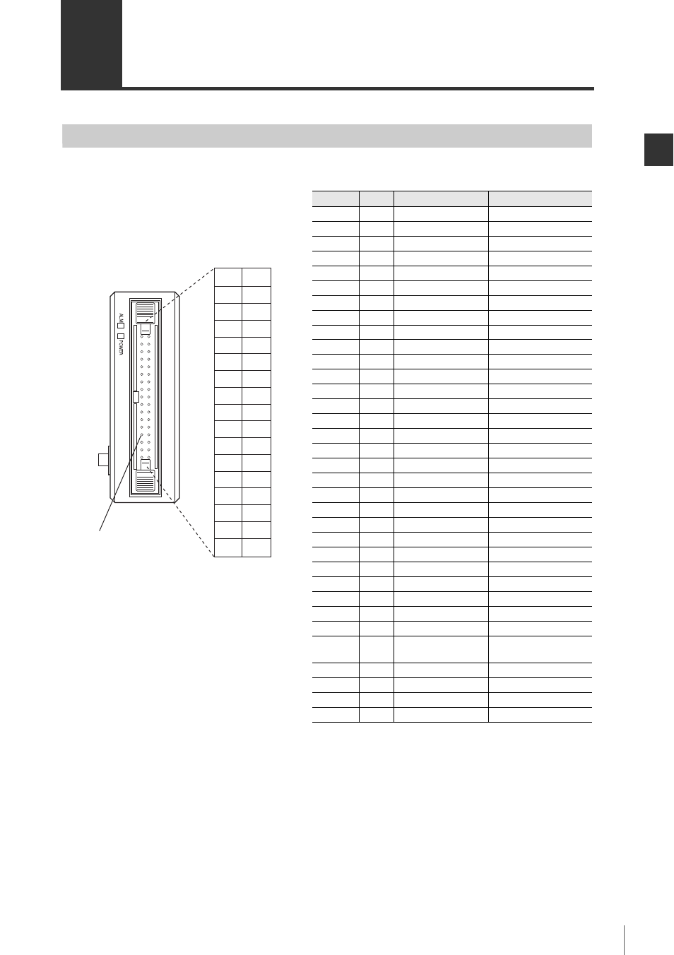
I/O Connector
This section describes the pin assignments and each signal on the I/O connector.
Pin No. Direction
Signal name
Description
1
Input
IDSEL1
ID No. selection input 1
2
Input
IDSEL2
ID No. selection input 2
3
Input
IDSEL3
ID No. selection input 3
4
Input
IDSEL4
ID No. selection input 4
5
Input
DRQ
Data request input
6
Output
BCD DIGIT 1 (1)
BCD 1st digit 1 x 10
0
7
Output
BCD DIGIT 1 (2)
BCD 1st digit 2 x 10
0
8
Output
BCD DIGIT 1 (4)
BCD 1st digit 4 x 10
0
9
Output
BCD DIGIT 1 (8)
BCD 1st digit 8 x 10
0
10
Output
BCD DIGIT 2 (1)
BCD 2nd digit 1 x 10
1
11
Output
BCD DIGIT 2 (2)
BCD 2nd digit 2 x 10
1
12
Output
BCD DIGIT 2 (4)
BCD 2nd digit 4 x 10
1
13
Output
BCD DIGIT 2 (8)
BCD 2nd digit 8 x 10
1
14
Output
BCD DIGIT 3 (1)
BCD 3rd digit 1 x 10
2
15
Output
BCD DIGIT 3 (2)
BCD 3rd digit 2 x 10
2
16
Output
BCD DIGIT 3 (4)
BCD 3rd digit 4 x 10
2
17
Output
BCD DIGIT 3 (8)
BCD 3rd digit 8 x 10
2
18
Output
BCD DIGIT 4 (1)
BCD 4th digit 1 x 10
3
19
Output
BCD DIGIT 4 (2)
BCD 4th digit 2 x 10
3
20
Output
BCD DIGIT 4 (4)
BCD 4th digit 4 x 10
3
21
Output
BCD DIGIT 4 (8)
BCD 4th digit 8 x 10
3
22
Output
BCD DIGIT 5 (1)
BCD 5th digit 1 x 10
4
23
Output
BCD DIGIT 5 (2)
BCD 5th digit 2 x 10
4
24
Output
BCD DIGIT 5 (4)
BCD 5th digit 4 x 10
4
25
Output
BCD DIGIT 5 (8)
BCD 5th digit 8 x 10
4
26
Output
BCD DIGIT 6 (1)
BCD 6th digit 1 x 10
5
27
Output
BCD DIGIT 6 (2)
BCD 6th digit 2 x 10
5
28
Output
BCD DIGIT 6 (4)
BCD 6th digit 4 x 10
5
29
Output
BCD DIGIT 6 (8)
BCD 6th digit 8 x 10
5
30
Output
BCD SIGN
BCD data polarity
code
31
Output
BCD STB
*1
Strobe output
32
Output
ALARM
*2
Alarm output
33
Common
COM
Common
34
Common
COM
Common
*1Be sure to load the BCD output (Pin Nos. 6 to 30) when the
strobe output (Pin No. 31) is turned on.
*2Alarm output will be turned off when the alarm is generated.
(It is turned on in normal conditions.)
Connector terminal area
I/O connector
1
3
5
7
9
11
13
15
17
19
21
23
25
27
29
31
33
2
4
6
8
10
12
14
16
18
20
22
24
26
28
30
32
34