1 before using the unit, Checking the package contents, Part names and functions – KEYENCE DL-RB1A User Manual
Page 8: Before using the unit
6
In
tro
du
ct
ion
1
1-1
Before Using the Unit
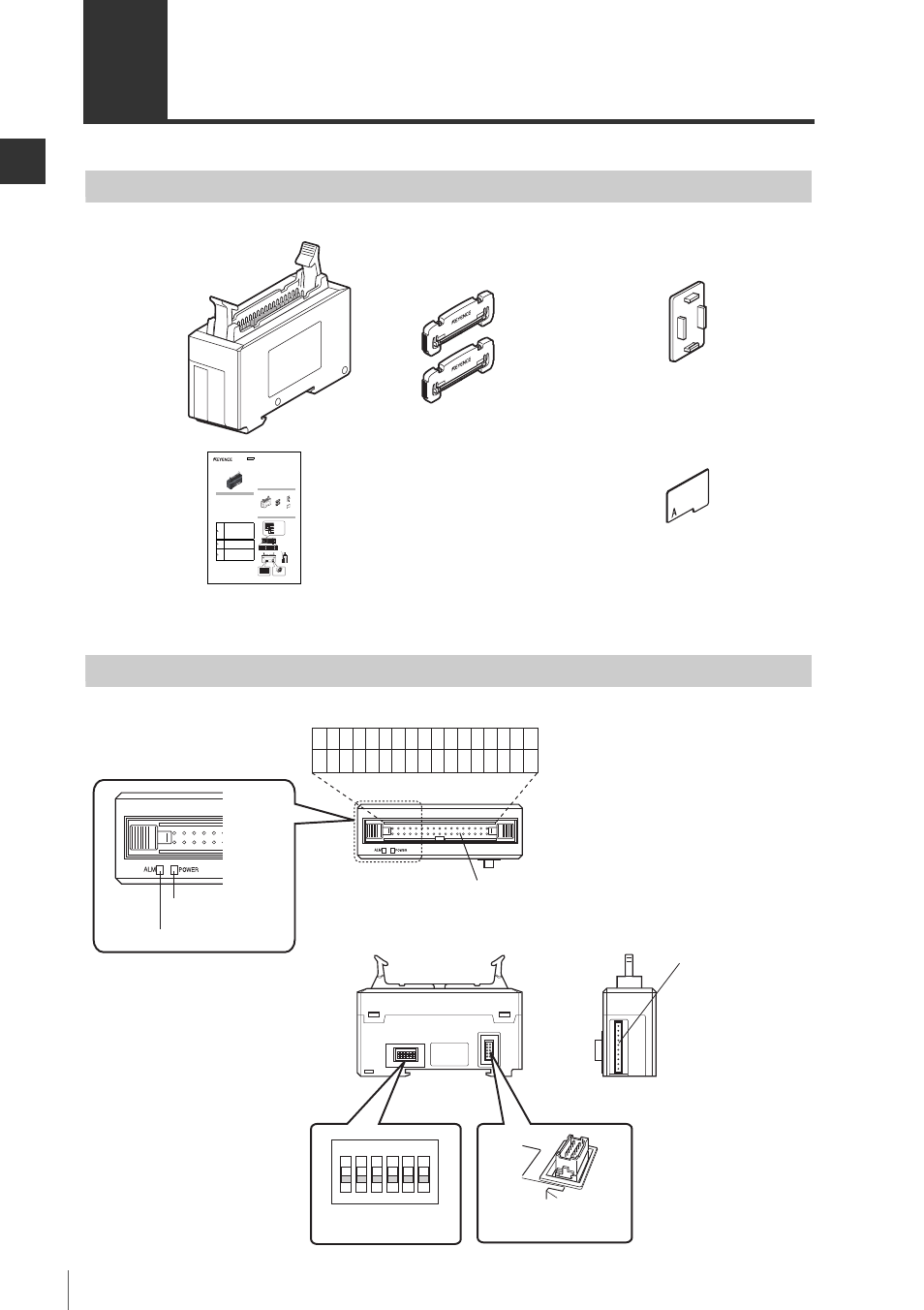
Checking the Package Contents
Before using the DL-RB1A, check that the following items are all included.
We have thoroughly inspected the package contents before shipment. However, in the event of
defective or broken items, please contact your nearest KEYENCE office.
Part Names and Functions
End units (x2)
OP-26751
BCD output unit
DL-RB1A
expansion connector cover
Switch protection sticker
1
BCD Output Unit
DL-RB1A
Instruction Manual
Safety Precautions
■ General Cautions
• At startup and during operation, be sure to monitor the functions and
performance of the DL-RB1A.
• Provide appropriate safety measures to avoid any damage in the event
that a problem occurs.
• Do not modify the DL-RB1A or use it in any way other than described in
the specifications. The functions and performance of products used or
modified in this way cannot be assured.
• When the DL-RB1A is used in combination with other instruments, its
functions and performance may be degraded, depending on the operating
conditions and surrounding environment. Use the DL-RB1A after fully
studying the effect of combined use with other instruments.
• Do not use the DL-RB1A for the purpose of protecting the human body.
• Do not expose the DL-RB1A and peripheral devices to sudden
temperature changes. This may cause condensation, damaging the
equipment.
z Proper environment and conditions
To use the DL-RB1A properly and safely, do not install the DL-RB1A
in locations with the following conditions. Use of this equipment in
an improper environment may cause equipment failure.
•
Locations with high humidity, a large amount of dust, or poor ventilation
•
Locations where the temperature rises excessively due to direct
sunlight, etc.
•
Locations where corrosive or flammable gas exists
•
Locations where the DL-RB1A is directly subjected to vibration or
impact
•
Locations where water, oil or chemicals may splash the DL-RB1A
•
Locations where static electricity is easily built up
z Noise countermeasures
Installation near a source of noise such as a power source and a
power cable may cause a malfunction or failure in the equipment.
Adopt appropriate countermeasures against noise by using a noise
filter or wiring cables in separate ducts, attaching insulation to the
sensor amplifier or the sensor head, etc.
Package Contents
The product package should include the following items. Check that all
items are included before use.
We made all possible cares in packaging; however, if any parts are found to
be defective or broken, please contact your nearest KEYENCE sales office.
Parts Names
WARNING
If the following conditions are encountered,
immediately turn off the power. Continuing to use
the DL-RB1A under abnormal conditions may
cause fire, electric shock or equipment failure.
• When water or foreign matter enters the
controller
• When the DL-RB1A is dropped or the housing
is damaged
• When the DL-RB1A produces smoke or an abnormal
smell
WARNING
• Do not use the DL-RB1A with a voltage other
than specified voltage, as this may cause fire,
electric shock or equipment failure.
• Do not disassemble or modify the DL-RB1A.
This may cause fire or electric shock.
CAUTION
• Be sure to turn off the power to the DL-RB1A
and any connected devices before connecting
or disconnecting the cables. Otherwise, there
may be a risk of damaging the unit.
• Do not turn off the power while setting a
parameter. Otherwise, the settings may be
partially or completely lost.
End unit x 2
OP-26751
Communication unit
DL-RB1A
Expansion connector cover
Switch protect sticker
Alarm indicator (red)
Power indicator (green)
Connector terminal area
Sensor amplifier connector
(for panel mounting type)*
I/O connector
Sensor amplifier connector
(for DIN rail mounting type)
*Sticker is attached.
Advanced setting switch
10 2# 3 4 5 6
G D
2 4 6 8 10 12 14 16 18 20 22 24 26 28 30 32 34
1 3 5 7 9 11 13 15 17 19 21 23 25 27 29 31 33
10 2
N
3 4 5 6
96M00248
Instruction manual
Connector terminals
(6) I/O connector
(1) Advanced setting
switches
(2) Sensor amplifier connector
(for DIN rail mounting)
(3) Sensor amplifier connector
10 2# 3 4 5 6
G D
10 2
N
3 4 5 6
2 4 6 8 10 12 14 16 18 20 22 24 26 28 30 32 34
1 3 5 7 9 11 13 15 17 19 21 23 25 27 29 31 33
(for panel mounting type/
large display type)*
(4) Alarm indicator (red)
(5) Power indicator
(green)