KEYENCE DL-RB1A User Manual
Page 18
16
M
ou
ntin
g an
d Co
nn
ec
tin
g the
D
L-
R
B
1A
2
2-1
Connecting the DL-RB1A to External Devices
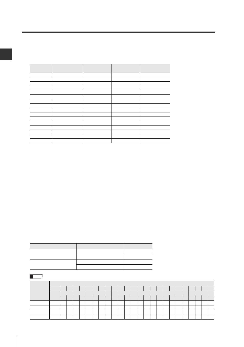
Pin Nos. 1 to 4: ID No. selection input
Select the ID number for the sensor amplifier that outputs data by changing the combination of input
signals that are turned on or off. For information about ID numbers, refer to "Sensor Amplifier ID
Number Assignments" (page 24).
*1 The IG Series and IB Series do not use ID No. 04 to 15.
The GT-70A Series does not use ID No. 10 to 14.
The IL Series and SK-1000 Series does not use ID No. 08 to 15.
ID No. 15 outputs the P.V. value for the main unit when using a calculation function other than
reference difference display on the GT2 Series or GT-70A Series. (During this time, ID No. 00
outputs the R.V. value for the main unit.)
For information about the calculation function, refer to the User's Manual of each sensor amplifier.
Pin No. 5: Data request input (DRQ)
Within 2 ms after the DRQ input is turned on, the data from the sensor amplifier with the selected ID
number is updated and output through BCD output. For more information, refer to "Chapter 3:
Advanced Functions" (Page 23).
Pin Nos. 6 to 30: BCD output and BCD data polarity code
Represents a signed six digit figure depending on the combination of outputs that are turned on or
off.
Set the DL-RB1A output logic with the advanced setting switch No. 1. For more information on
advanced setting switches, refer to "Part Names and Functions" (page 6).
The following table shows examples of BCD output (pin Nos. 6 to 30).
ID No.
*1
Pin No. 4
IDSEL4
Pin No. 3
IDSEL3
Pin No. 2
IDSEL2
Pin No. 1
IDSEL1
00
0
0
0
0
01
0
0
0
1
02
0
0
1
0
03
0
0
1
1
04
0
1
0
0
05
0
1
0
1
06
0
1
1
0
07
0
1
1
1
08
1
0
0
0
09
1
0
0
1
10
1
0
1
0
11
1
0
1
1
12
1
1
0
0
13
1
1
0
1
14
1
1
1
0
15
1
1
1
1
Output logic
Transistor output
Bit
Negative logic
(Factory default)
OFF
0
ON
1
Positive logic
ON
0
OFF
1
Detection
data from
the sensor
amplifiers
Pin No.
30
29
28 27
26 25
24 23
22
21
20
19
18
17
16
15
14
13
12
11
10
9
8
7
6
Signed
BCD 6th digit
BCD 5th digit
BCD 4th digit
BCD 3th digit
BCD 2nd digit
BCD 1st digit
8
4
2
1
8
4
2
1
8
4
2
1
8
4
2
1
8
4
2
1
8
4
2
1
+000000
0
0
0
0
0
0
0
0
0
0
0
0
0
0
0
0
0
0
0
0
0
0
0
0
0
+123456
0
0
0
0
1
0
0
1
0
0
0
1
1
0
1
0
0
0
1
0
1
0
1
1
0
-123456
1
0
0
0
1
0
0
1
0
0
0
1
1
0
1
0
0
0
1
0
1
0
1
1
0
+ABCDEF
0
1
0
1
0
1
0
1
1
1
1
0
0
1
1
0
1
1
1
1
0
1
1
1
1
* When the output logic is negative logic, the output is turned off for 0 and turned on for 1.
When the output logic is positive logic, the output is turned on for 0 and turned off for 1.
Reference