Electrical installation -10 – Hardy HI 200DNWM DeviceNet Weigh Module User Manual
Page 26
HI 200DNWM MANUAL
3-10
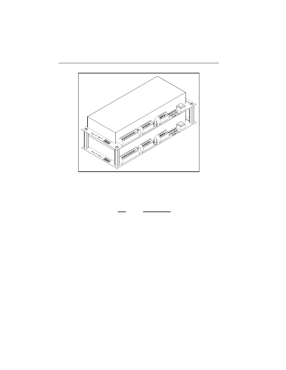
FIG. 3-9 INSTALLING THE STACKING KIT
Electrical
Installation
Wiring Diagram
for the J1 Load
Sensor 8 Pin
Connector
Pin
Description
1
-C2
2
+C2
3
-EXC (Minus Excitation
4
-SEN (Minus Sense)
5
-SIG (Minus Signal)
6
+SIG (Plus Signal)
7
+SEN (Plus Sense)
8
+EXC (Plus Excitation) +5VDC
NOTE:
If the sense lines are not used to measure the actual
excitation voltage at the junction box, an error is
introduced. The error is equal to the percentage of
excitation voltage lost between the instrument and the
junction box. If the excitation voltage at the back of