Brookfield RST Rheometer User Manual
Page 9
Brookfield Engineering Labs., Inc.
page 9
Manual No. M14-223
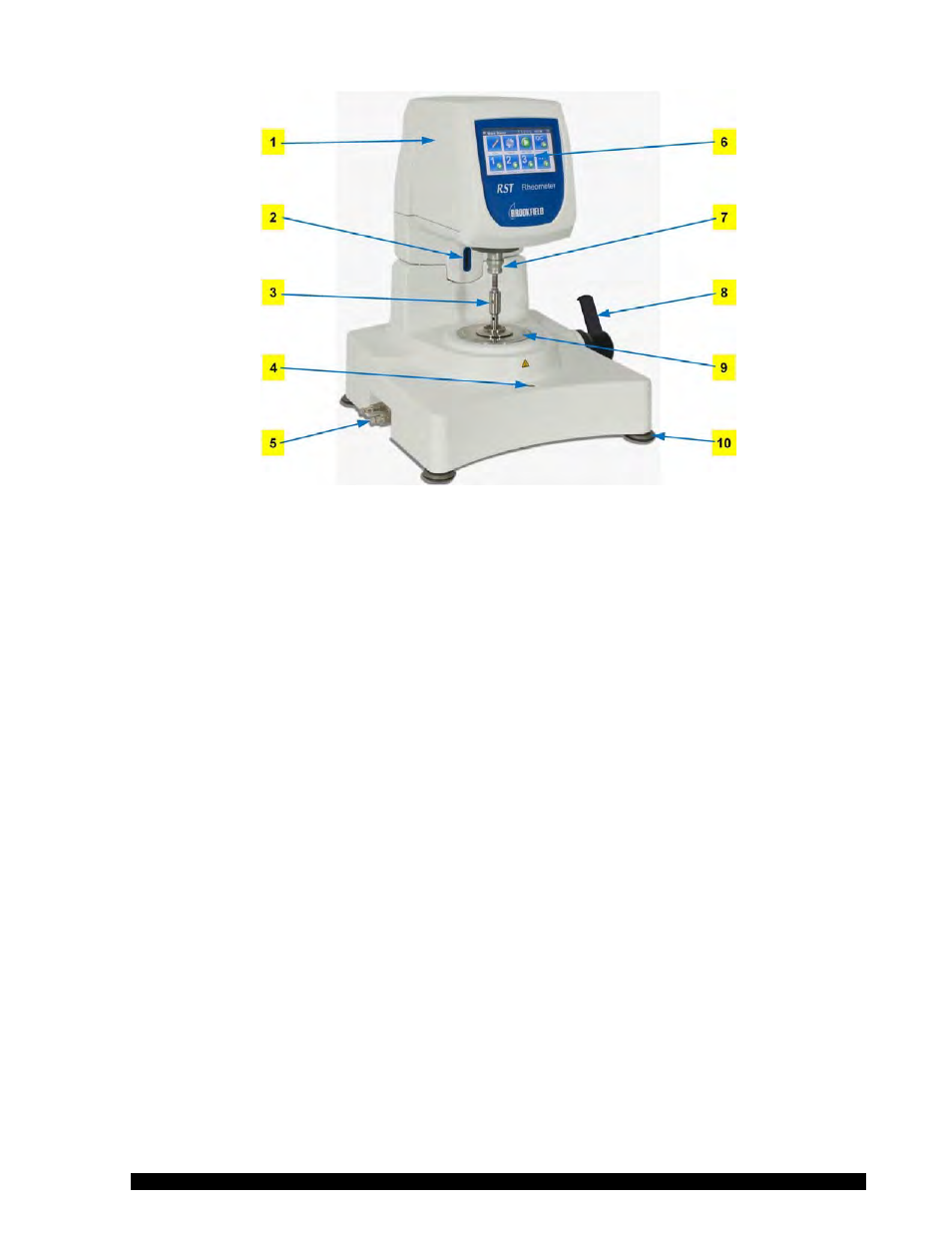
Figure I-3
Components:
1 Measuring Head
6 Touch Screen Display
2 Barcode Reader
7 Measuring Spindle Coupling
3 Spindle (Cone or Plate)
8 Lever
4 Bubble Level
9 Measuring Bottom Plate
5 Hose Connectors (RST-CPS-F)
10 Levelling Screw
I.2.5 Elements for RST-CPS
Measuring devices are not part of the standard delivery of the RST-CPS Rheometer and must be ordered
according to your measuring requirements. The following types of measuring systems are suited for use
with the RST-CPS Rheometer:
a) cone/plate measuring systems
b) plate/plate measuring systems
c) Please select a suitable measuring system in the measuring range required for your
measurements (see Appendix E).
When measuring cones are used the shear rate is the same across the whole measuring gap. The
most common cone angles are =1° and
!=2°. The cone is truncated 50µm (0.05 mm) in order
to avoid contact and friction with the bottom measuring plate.
Measuring plates are used when larger filling particles occur in the measured substance. Gaps
between 0.1 to 3.0 mm may be used. In this case, the shear rate in the measuring gap is a function
of the radius.