Ii.4.5.2 assembly of cone/plate measuring system – Brookfield RST Rheometer User Manual
Page 18
Brookfield Engineering Labs., Inc.
page 18
Manual No. M14-223
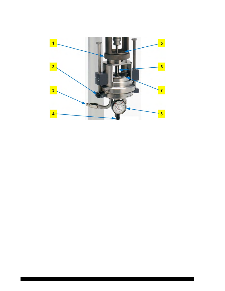
II.4.5.2 Assembly of Cone/Plate Measuring System
Figure II-4
Components:
1 Threaded joint for mounting flange
5 Guide pin
2 Quarter-turn fastener
6 Measuring bob
3 Hose connectors for thermostatting medium
7 Measuring table
4 Adjusting screw
8 Gauge
The RST Rheometer enables you to determine viscosity using a cone/plate or plate/plate
system with the measuring device ME3-CP/PP. To install this optional measuring system,
proceed as follows:
• Turn the RST Rheometer off with the mains switch on the back of the instrument
• If the KE cooling unit is to be used, mount it first.
• Set the ME3-CP/PP on the rheometer flange from below and tighten the thread.
• Before tightening the thread, check to see if the guide pin of the measuring plate lies
in the groove of the mounting flange of the RST.
• Connect hoses to the liquid circulation thermostat (see below).
• Plug the cable of the built-in Pt100 into the socket “Pt100” on the back panel of the
RST Rheometer.
Hose connection from thermostat to measuring device ME3-CP/PP:
• Hose connections are required to connect a liquid circulation thermostat when the
RST Rheometer is operated with the cone/plate measuring device ME3-CP/PP.
• The hoses from the liquid circulation thermostat are connected with the cone/plate
measuring device ME3-CP/PP using the quick-fitting couplings. For that purpose you
push the coupling sleeve slightly back, insert the hose connector and let the coupling
go. It will fasten the hose (without screwing or turning) by locking in. Pull lightly to
check if the hoses fit tightly.