Brookfield RST Rheometer User Manual
Page 15
Brookfield Engineering Labs., Inc.
page 15
Manual No. M14-223
II.4.3 Mounting the Workplate RST-SST
This step is required only if you intend to use the workplate of the RST-SST. To mount it, proceed as
follows:
• Place the workplate into the upper or lower seat by pushing it in laterally until it stops.
• Screw the work plate to the stand finger-tight using the two spigot nuts.
• Put the sliding blocks with the threaded rods through the slots in the work plate from below. Make
sure that the groove of the sliding block fits into the slot.
• Use the thumb wheel to screw the fastening claw down finger-tight.
• For each slot you will need 1 fastening claw, 1 sliding block with threaded rod and 1 thumb wheel.
II.4.4 Electrical Connections RST-CC and RST-SST
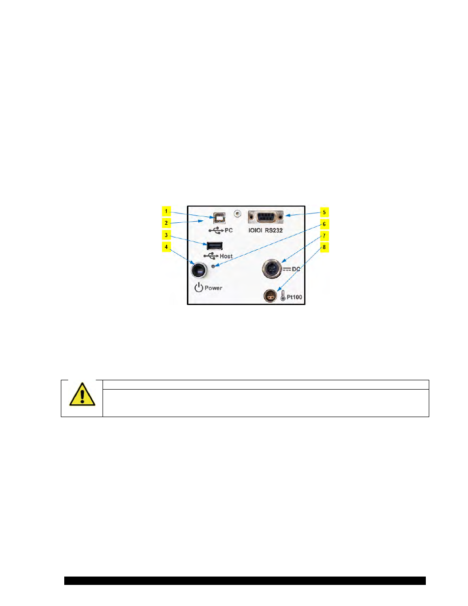
Connections for the electrical components of the RST Rheometer are located on the back of the
instrument.
Figure II-1
Connecting elements on the back of the instrument in Figure II-8:
1 PC (USB)
5 RS 232 port
2 LAN (network)
6 ON / OFF control light
3 USB stick or printer
7 Power unit (AC adapter)
4 ON / OFF button
8 Pt100 temperature sensor
Caution!
Connecting the measuring instrument
Connect or disconnect any cables from and to the RST Rheometer only with the instrument
turned off.
II.4.5 RST-CC and RST-SST Assembly for Additional Devices
This section describes assembly and connection of the following measuring systems:
• FTK temperature-control device (water jacket) for use of cylinder measuring systems in the
temperature range of -10°C...+90°C (temperature control by liquid thermostat)
• ME3-CP/PP measuring device for cone/plate and plate/plate measuring systems in the
temperature range of -10°C...+90°C (temperature control by liquid thermostat)
• KE cooling device in connection with FTK temperature-control device (water jacket) or ME3-
CP/PP measuring device for extension of temperature range to -20°C...+180°C