Installation guidelines – Waterworks Universal 1/2" Thermostatic Valve User Manual
Page 3
PRODUCT SUPPORT 800.927.2120 8am - 6pm EST
UNIVERSAL
1/2" THERMOSTATIC VALVE
INSTALLATION GUIDELINES
Page 3 of 3
6.13.2014
These guidelines have been prepared for the professional contractor to aid in the installation of:
UNIVERSAL 1/2" THERMOSTATIC VALVE STYLE NO. GUTH56, GU56TH (UK)
All dimensions are based on original specification and are subject to change and variation.
Please consult your Design Associate for current specifications.
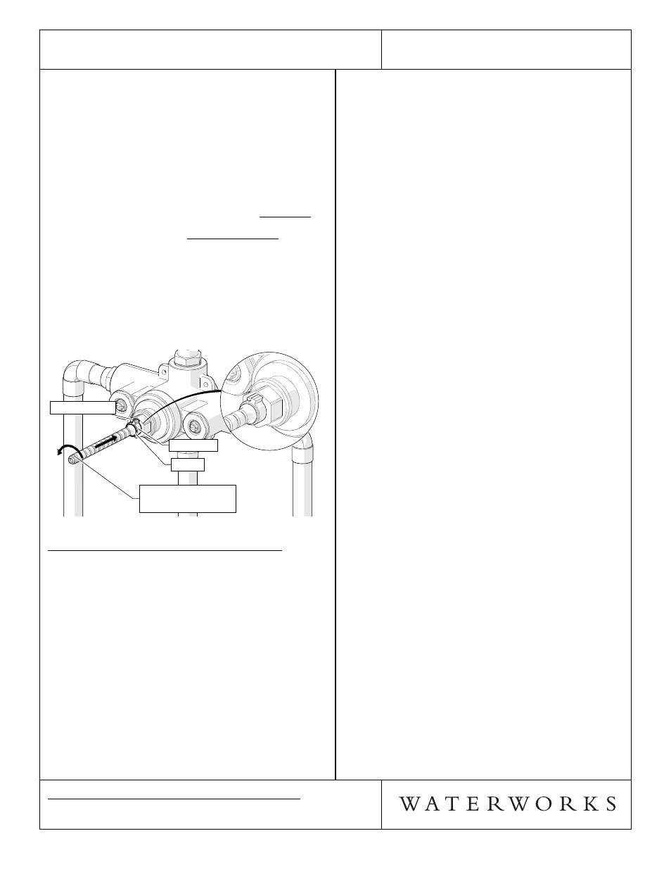
¾ See Figure - 05 & Figure - 06 for steps 13-16.
13. Turn on the water supply and a wall valve to run
water through the valve.
14. Slowly rotate the CARTRIDGE STEM clockwise to
attain full cold, then rotate it counterclockwise to
attain full hot. Verify that a full range of
temperatures exists. Note: It is approximately 3/4 of
a rotation from full cold to hot.
15. With the water running, rotate the CARTRIDGE
STEM to adjust the temperature to the MAXIMUM
desired bathing temperature, verified with a
thermometer. Note: It is not recommended to
exceed 110°F.
16. With the CARTRIDGE STEM at the maximum desired
bathing temperature, slide the LIMIT STOP back
onto the CARTRIDGE STEM, making sure that it is
making contact with the LIMIT STOP PIN. Slide the
O-RING back to its original position to prevent the
LIMIT STOP from sliding off the stem; then turn off
the water.
LIMIT STOP PIN
LIMIT STOP
O-RING
CARTRIDGE STEM
AT MAXIMUM DESIRED
HOT TEMPERATURE
LIMIT STOP PIN
LIMIT STOP
O-RING
CARTRIDGE STEM
AT MAXIMUM DESIRED
HOT TEMPERATURE
FIGURE - 06
INSPECT THE CALIBRATION & INSTALLATION:
17. Turn the CARTRIDGE STEM clockwise, then turn the
water on and confirm that the LIMIT STOP is
functioning properly by turning it counterclockwise
at which point it should hit the PIN and stop.
18. Verify the temperature to be the maximum
temperature set in Step 15. If it is not the correct
temperature, repeat the calibration process.
19. Reinstall the THREADED TUBE back onto the
VALVE BODY.
20. Reinstall the TILE GUARD using the SCREWS to
complete this installation.
¾ If further assistance is required, please contact
Product Support at 1-800-927-2120 (8am-6pm EST).
¾ See service part document for parts ordering,
available on WATERWORKS.COM.
† BSP Adapters can be ordered separately:
STYLE No. UNUK02
ITEM No. 45-57632-24328