Installation guidelines, Universal – Waterworks Universal 1/2" Thermostatic Valve User Manual
Page 2
PRODUCT SUPPORT 800.927.2120 8am - 6pm EST
UNIVERSAL
1/2" THERMOSTATIC VALVE
INSTALLATION GUIDELINES
Page 2 of 3
6.13.2014
These guidelines have been prepared for the professional contractor to aid in the installation of:
UNIVERSAL 1/2" THERMOSTATIC VALVE STYLE NO. GUTH56, GU56TH (UK)
All dimensions are based on original specification and are subject to change and variation.
Please consult your Design Associate for current specifications.
7. The bottom port of the valve body is not plugged
and can be used to supply water to other fittings.
Install a 1/2" NPT plug (not supplied) if the port will
not be used.
8. Install the TILE GUARD to protect the valve during
the completion of the finished wall and to create the
exact opening for access to the service stops and
future servicing.
VALVE
BODY
1/2" MALE
NPT ADAPTER
Pre-Soldered to pipe.
(Not Supplied)
BOTTOM PORT
(Plug if not being used)
MOUNTING TAB
4X
TILE
GUARD
SCREWS
VALVE
BODY
1/2" MALE
NPT ADAPTER
Pre-Soldered to pipe.
(Not Supplied)
BOTTOM PORT
(Plug if not being used)
MOUNTING TAB
4X
TILE
GUARD
SCREWS
FIGURE - 04
INSPECT THE INSTALLATION:
9. Remove TILE GUARD and turn on water supply and
inspect all connections for leaks.
10. Turn off the water supply and turn off the SERVICE
STOPS, seen in Figure-02.
11. Reinstall TILE GUARD.
TEMPERATURE CALIBRATION:
¾ The risk of scalding exists until the installer has
properly calibrated/adjusted the temperature
setting prior to final trim installation.
12. Remove the TILE GUARD and THREADED TUBE.
Slide the O-RING and LIMIT STOP up the
CARTRIDGE STEM. DO NOT REMOVE OR DAMAGE
THE O-RING. See Figure - 05.
OUTLET
TO VOLUME
CONTROL
OR DIVERTER
VALVE
(SOLD SEPARATELY)
OUTLET
TO VOLUME CONTROL
OR DIVERTER VALVE
(SOLD SEPARATELY)
LIMIT STOP PIN
LIMIT STOP
O-RING
CARTRIDGE
STEM
THREADED
TUBE
OUTLET
TO VOLUME
CONTROL
OR DIVERTER
VALVE
(SOLD SEPARATELY)
OUTLET
TO VOLUME CONTROL
OR DIVERTER VALVE
(SOLD SEPARATELY)
LIMIT STOP PIN
LIMIT STOP
O-RING
CARTRIDGE
STEM
THREADED
TUBE
HOT
COLD
FIGURE - 05
TOP
OUTLET
BOTTOM
OUTLET
SERVICE
STOPS
TOP
OUTLET
BOTTOM
OUTLET
SERVICE
STOPS
C
H
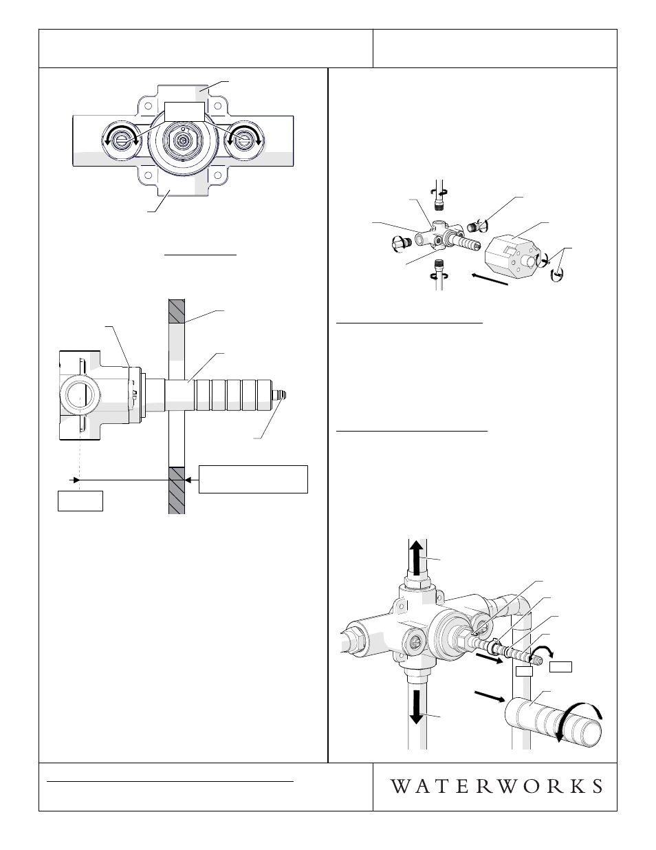
FIGURE - 02
3. IMPORTANT: Valve rough-in depth is measured
from the center of the inlets to the surface of the
finished wall and varies depending on the trim used.
See Figure - 03
VALVE
BODY
FINISHED
WALL
CARTRIDGE
STEM
THREADED
TUBE
VALVE
BODY
FINISHED
WALL
CARTRIDGE
STEM
THREADED
TUBE
ROUGH-IN DEPTH
3-1/4" MIN - 4-1/4" MAX
(83mm MIN - 108mm MAX)
CENTER
OF INLETS
FIGURE - 03
¾ See Figure - 04 for steps 4-8.
4. Run 1/2" (15mm) copper supply lines to the proper
height of the valve inlets and be sure to secure all
piping and fittings.
¾ Note: The valve body has 4 mounting tabs; 2 of
these tabs are used to hold the tile guard to the
valve body and the other 2 can be used to secure
the valve body to adequate blocking.
5. DO NOT APPLY DIRECT HEAT TO THE VALVE. Pre-
solder 1/2" male NPT adapters (not supplied) prior
to threading into the valve body.
6. For each fitting that will have water flowing to it,
install a wall valve or diverter valve (both sold
separately) at the same rough in depth and
according to the flow direction arrow marked on the
wall valve or diverter valve body.