Installation guidelines – Waterworks Formwork Floor Mounted Exposed Tub Filler with Handshower and Metal Jostick Handle User Manual
Page 2
PRODUCT SUPPORT 800.927.2120 8am - 6pm EST
FORMWORK
Floor Mounted Exposed Tub Filler
Installation Guidelines
Page 2 of 4
Rev - 01
8.18.2014
These guidelines have been prepared for the professional contractor to aid in the installation of:
FORMWORK FLOOR MOUNTED EXPOSED TUB FILLER WITH METAL JOYSTICK HANDLE [STYLE No. FMXT70,
FM70XT (UK)] & FORMWORK FLOOR MOUNTED EXPOSED TUB FILLER WITH HANDSHOWER AND METAL
JOYSTICK HANDLE [STYLE No. FMXT90, FM90XT (UK)]
All dimensions are based on original specification and are subject to change and variation.
Please consult your Design Associate for current specifications.
1. Determine the location of the MOUNTING PLATE and
install adequate blocking to properly secure the
MOUNTING PLATE.
A Ø3-7/8" hole is required for proper installation of
the spout.
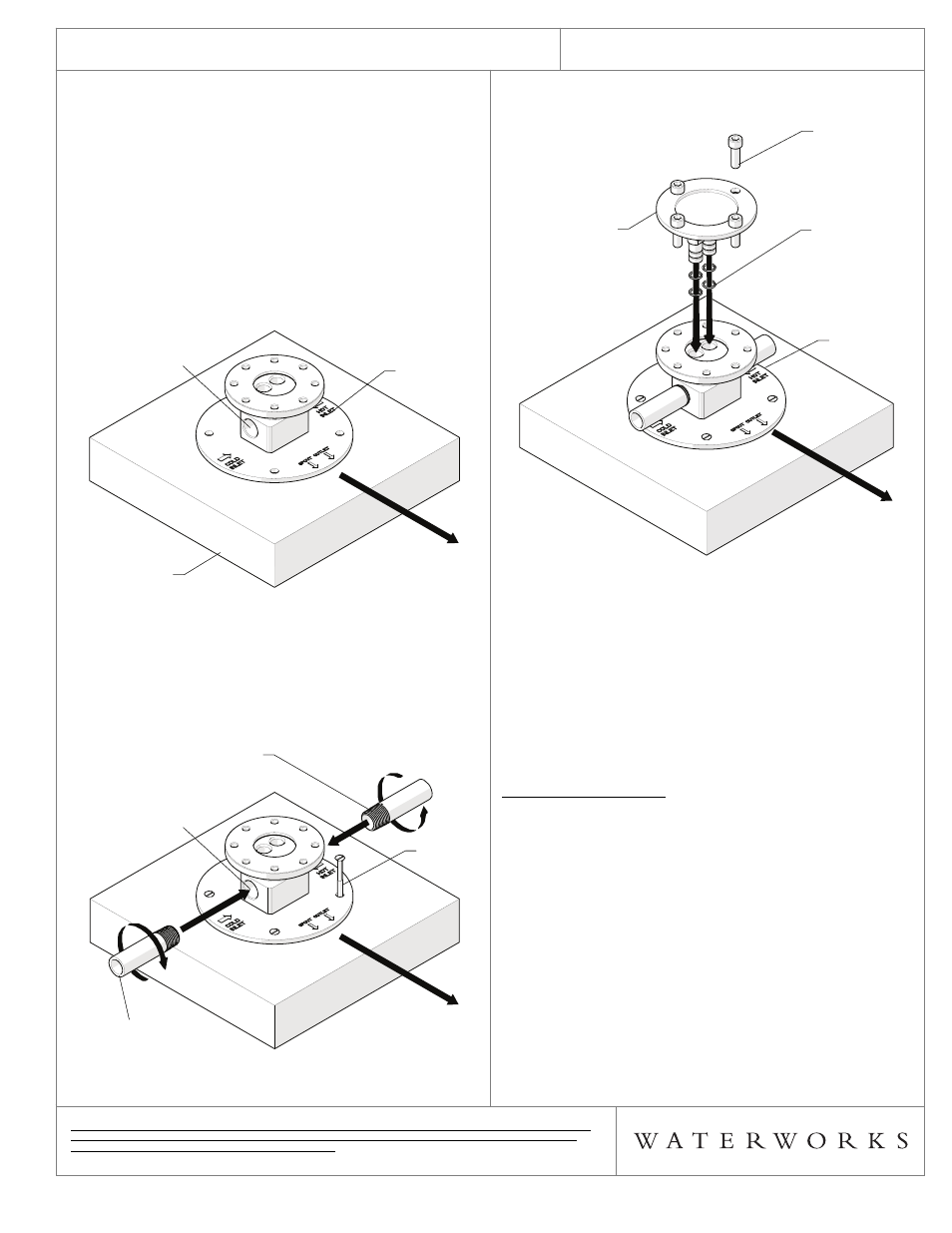
2. Place the MOUNTING PLATE on the blocking with the
inlets perpendicular to the SPOUT and towards the
opposite direction of the tub as shown in Figure- 02.
“Cold Inlet”, “Hot Inlet” and “Spout Outlet” direction
markings are also located on MOUNTING PLATE. The
cold inlet is located on the left and the hot inlet is on
the right.
FIGURE - 02
3. Thread and securely tighten 1/2" male NPT hot and
cold supply lines into the MOUNTING PLATE then
secure the MOUNTING PLATE to the sub-floor using 4
SCREWS (not supplied) as shown in Figure - 03.
The MOUNTING PLATE has 4 pre-drilled holes.
FIGURE - 03
MOUNTING
PLATE
1/2" FEMALE NPT INLETS
PERPENDICULAR TO
THE SPOUT
BLOCKING
MOUNTING
PLATE
1/2" FEMALE NPT INLETS
PERPENDICULAR TO
THE SPOUT
BLOCKING
SPOUT DIRECTION
TOWARDS TUB
HOT SUPPLY
SCREW
1/2" FEMALE NPT INLETS
PERPENDICULAR TO
THE SPOUT
COLD SUPPLY
HOT SUPPLY
SCREW
1/2" FEMALE NPT INLETS
PERPENDICULAR TO
THE SPOUT
COLD SUPPLY
SPOUT DIRECTION
TOWARDS TUB
4. Finish all connections below the finished floor and
install the TEST PLATE using the SCREWS provided as
shown in Figure - 04.
FIGURE – 04
5. Turn on the water supply lines and check for leaks.
6. Turn off the water supply lines. DO NOT remove the
TEST PLATE.
7. Tile up to the TEST PLATE. DO NOT tile over the TEST
PLATE
IMPORTANT: A Ø3-7/8" hole is required to properly
install the spout.
SPOUT INSTALLATION:
8. Remove the TEST PLATE from the MOUNTING PLATE.
9. Slide the ESCUTCHEON up the SPOUT to expose the
SPOUT FLANGE then insert the SUPPY TUBES into the
MOUNTING PLATE as shown in Figure - 05. Make sure
the O-RINGS are properly attached to the SUPPLY
TUBES.
Do not twist or turn the SPOUT. This could damage the
SUPPLY TUBES.
O-RING
MOUNTING
PLATE
SCREW
TEST PLATE
O-RING
MOUNTING
PLATE
SCREW
TEST PLATE
SPOUT DIRECTION
TOWARDS TUB