Waterworks Easton Classic Low Profile Concealed Tub Filler With Handshower and White Porcelain Lever Handles User Manual
Installation guidelines
2
3
/
8
"
3"
5"
1
5
/
8
"
max
2"
max
3
3
/
4
"
3"
max
6"
10"
8
1
/
2
"
2
1
/
4
"
24" hose
78" hose
3
/
4
" NPT
3
1
/
2
"
3
3
/
4
"
Ш
2
3
/
8
"
3
1
/
2
"
3
3
/
4
"
Ш
2
3
/
8
"
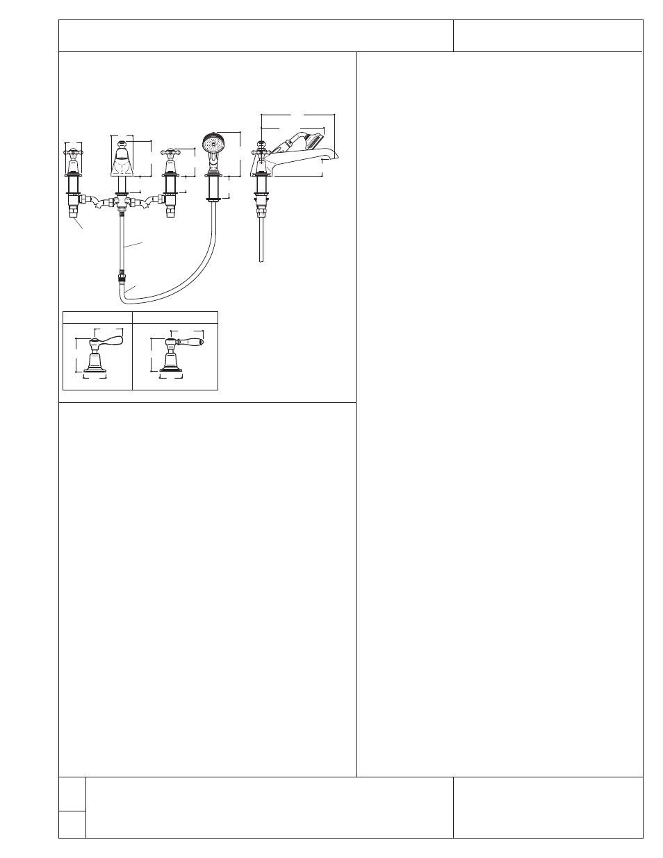
EATU02-K
EATU03-K, 04-K, 05K
Notes:
• Inlets are
3
/
4
" straight
male thread - NPT
adaptors provided
• Drilling hole size: 1
1
/
2
"
• Must have access panel
for servicing.
• Consult your local
building codes for
anti-scald requirements.
Easton
®
Concealed Tub Filler with Hand Shower - Covered
These guidelines have been prepared for the professional contractor to aid in the installation of:
EASTON
®
CONCEALED TUB FILLER WITH HAND SHOWER (COVERED)
(EATU01, 02-K, 03-K, 04-K, 05-K)
All dimensions are based on original specifications and are subject to change and variation.
Please consult your Design Associate for current specifications.
Installation Guidelines
1
W A T E R W O R K S
®
12/24
COVERED
EATU01 (CROSS HANDLE)
EATU02-K (METAL LEVER HANDLE)
EATU03-K (WHITE PORCELAIN LEVER HANDLE)
EATU04-K (BLACK PORCELAIN LEVER HANDLE)
EATU05-K (OAK LEVER HANDLE)
INSTALLATION GUIDELINES:
IMPORTANT:
➢
➢ T
To
o e
en
nssu
urre
e tth
hiiss p
prro
od
du
ucctt iiss iin
nssttaalllle
ed
d p
prro
op
pe
errllyy,, yyo
ou
u m
mu
usstt rre
eaad
d aan
nd
d
ffo
ollllo
ow
w tth
he
esse
e ggu
uiid
de
elliin
ne
ess..
➢
➢ T
Th
he
e o
ow
wn
ne
err//u
usse
err o
off tth
he
e ffaau
ucce
ett m
mu
usstt kke
ee
ep
p tth
hiiss iin
nffo
orrm
maattiio
on
n ffo
orr
ffu
uttu
urre
e rre
effe
erre
en
ncce
e..
➢
➢ B
Be
e ssu
urre
e yyo
ou
urr iin
nssttaallllaattiio
on
n cco
on
nffo
orrm
mss tto
o llo
occaall cco
od
de
ess.. IItt iiss tth
he
e
rre
essp
po
on
nssiib
biilliittyy o
off tth
he
e p
pllu
um
mb
be
err tto
o p
prro
ovviid
de
e aan
nttii--ssccaalld
d p
prro
otte
eccttiio
on
n..
➢
➢ A
Acccce
essssiib
blle
e ssh
hu
utt--o
offff vvaallvve
ess,, w
wh
hiicch
h w
wiillll ffaacciilliittaatte
e sse
errvviicciin
ngg,, aarre
e
rre
ecco
om
mm
me
en
nd
de
ed
d ffo
orr tth
he
e h
ho
ott aan
nd
d cco
olld
d ffe
ee
ed
d lliin
ne
ess..
➢
➢ A
An
n aacccce
essss p
paan
ne
ell iiss n
ne
ecce
essssaarryy ffo
orr ffu
uttu
urre
e sse
errvviicciin
ngg..
➢
➢ IInnssppeecctt tthhiiss pprro
od
du
ucctt tto
o aassssu
urre
e yyo
ou
u h
haavve
e aallll p
paarrttss rre
eq
qu
uiirre
ed
d ffo
orr
p
prro
op
pe
err iin
nssttaallllaattiio
on
n..
➢
➢ U
Usse
e o
on
nllyy aa ssttrraap
p w
wrre
en
ncch
h o
orr p
prro
otte
ecctte
ed
d//ssm
mo
oo
otth
h--jjaaw
w w
wrre
en
ncch
h o
on
n
aan
nyy ffiin
niissh
he
ed
d ssu
urrffaacce
e..
➢
➢ R
Ru
un
n 3
3//4
4"" ssu
up
pp
pllyy lliin
ne
ess ffo
orr m
maax
xiim
mu
um
m w
waatte
err ffllo
ow
w..
➢
➢ D
Do
o N
NO
OT
T u
usse
e p
pu
uttttyy d
du
urriin
ngg tth
hiiss iin
nssttaallllaattiio
on
n..
➢
➢ R
Re
effe
err tto
o tth
he
e ssp
pe
ecciiffiiccaattiio
on
n aan
nd
d aasssse
em
mb
bllyy d
drraaw
wiin
nggss aattttaacch
he
ed
d..
FFaau
ucce
ett iiss sso
olld
d p
paarrttiiaallllyy aasssse
em
mb
blle
ed
d b
bu
utt ssh
ho
ow
wn
n ffu
ullllyy d
diissaasssse
em
mb
blle
ed
d
ffo
orr iillllu
ussttrraattiivve
e aan
nd
d sse
errvviicce
e p
pu
urrp
po
osse
ess o
on
nllyy..
SIDE VALVE INSTALLATION:
1. With the lock nut (15) and lower sealing gasket (14) installed
on the side valve (13), insert the side valve into the hole in
the mounting surface so at least 1" of threads are exposed
above the deck surface.
2. Place the upper sealing gasket (11) onto the side valve then
thread the base escutcheon (10) onto the side valve.
3. Thread the handle assembly (1-9) onto the side valve until it
stops. Hand tight is adequate; if this assembly is too tight, the
handle will bind.
4. Unthread the base escutcheon until it contacts the gland nut
(6), which will assure proper side valve height.
5. Tighten the lock nut up against the underside of the
mounting surface to secure the side valve.
6. Repeat these steps to install the second side valve.
SPOUT INSTALLATION:
7. Unthread the diverter tee (32), locking nut (30) and lower
washer (29) from the spout (19).
8. Insert the spout assembly (17-28) through the hole in the
mounting surface with the upper washer (20) positioned
under the spout.
9. Reinstall the lower washer and tighten the locking nut to
secure the spout to the mounting surface.
10. Reattach the tee to the spout and fully tighten to prevent
leaks.
HAND SHOWER INSTALLATION:
11. Unscrew the locking nut (37) from the all-thread (42) and
remove the lower washer (38).
12. Unscrew the cover ring (44) from the all-thread and pull out
the plastic guide (43).
13. Insert the all-thread through the mounting surface, leaving
the escutcheon (41) and upper washer (40) in place.
14. Re-attach the lower washer and locking nut to the all-thread.
Fully tighten the locking nut to secure the assembly.
15. Slide the cover ring (44) over the conical end of the hose (36)
and insert the hose into the plastic guide (43). Now pass the
knurled end of the hose (36) through the all thread (42) until
the plastic guide is fully seated inside of the all-thread. Finally, re-
attach the cover ring to the all-thread.
16. Connect the conical end of the hose to the hand shower.
Note:The combination flow restrictor/non-return valve (45)
is located in the end of the hand shower.Final Connections
and Inspection