Waterworks Ludlow Volume Control Valve Trim with Metal Lever Handle User Manual
Installation guidelines, Ludlow
PRODUCT SUPPORT 800.927.2120 8am - 6pm EST
LUDLOW
Volume Control Valve Trim
INSTALLATION GUIDELINES
Page 1 of 2
10.30.2013
These guidelines have been prepared for the professional contractor to aid in the installation of:
LUDLOW VOLUME CONTROL VALVE TRIM WITH METAL CROSS HANDLE (STYLE# LDVC01) &
METAL LEVER HANDLE (STYLE # LDVC10)
All dimensions are based on original specification and are subject to change and variation.
Please consult your Design Associate for current specifications.
SEE SERVICE PART DOCUMENT FOR PART ORDERING, AVAILABLE ON WATERWORKS.COM
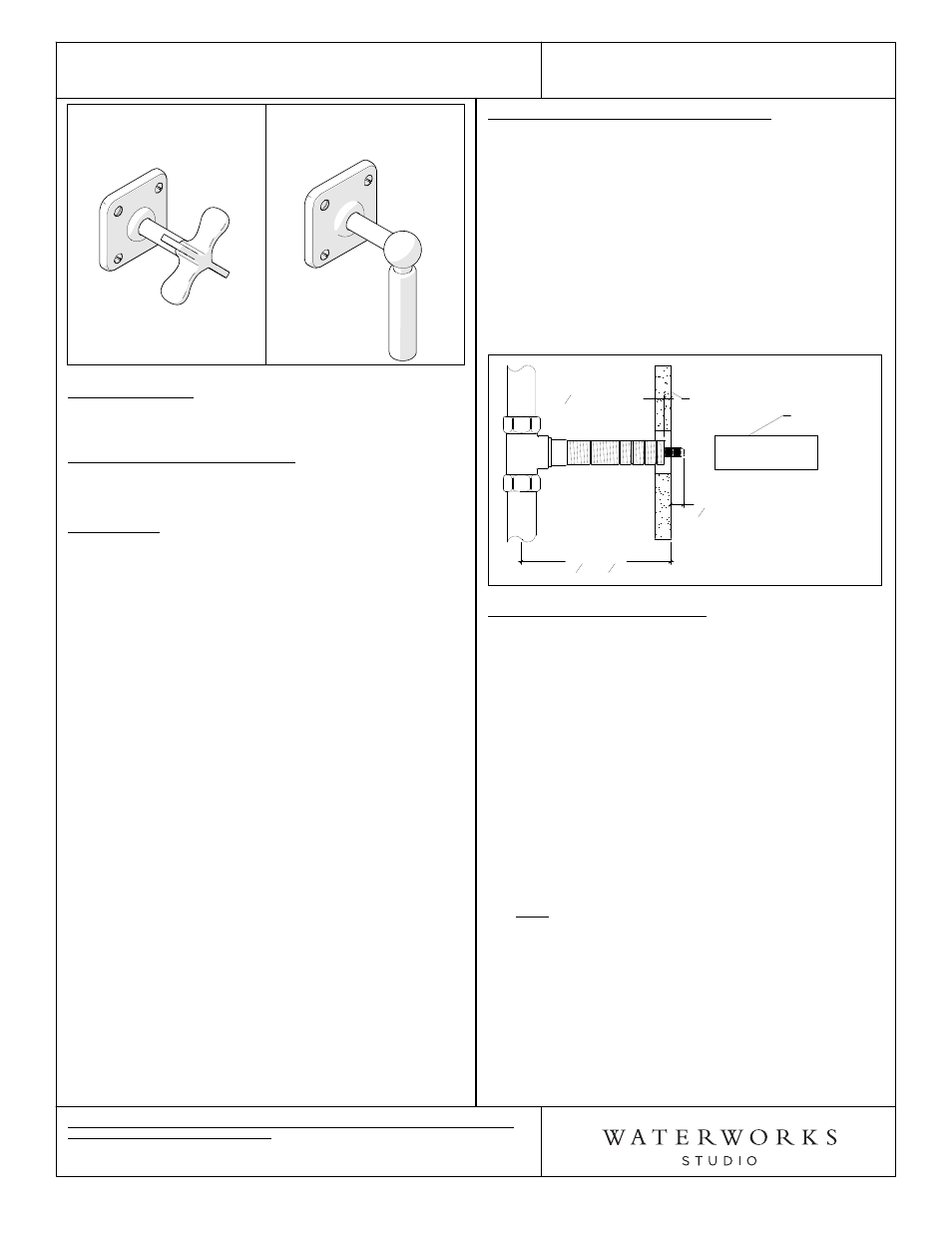
Metal Cross Handle
Style No. LDVC01
Metal Lever Handle
Style No. LDVC10
SPECIFICATIONS:
Control Valve Rough-in Depth Minimum: 3-1/4"
Control Valve Rough-in Depth Maximum: 4-1/4"
REQUIRED PLUMBING DETAILS:
1/2" Volume Control Valve
STYLE # GUVC18 or GUVC19
IMPORTANT:
¾ The screws on the escutcheons are aesthetic and do
not serve any mechanical purposes, and should not
be removed.
¾ To ensure this product is installed properly, you
must read and follow these guidelines.
¾ The owner/user of this product must keep this
information for future reference.
¾ Be sure your installation conforms to federal state,
and local codes. In the State of Massachusetts, all
installations must comply with the rules and
regulations set forth within 248 CMR.
¾ This product must be installed by a professional
licensed contractor and must be onsite prior to
rough-in, this allows the installer to visualize the
installation.
¾ Wall valves control on/off/volume and must be
installed for each fitting that will have water flowing
to it. If using a wall valve with the Universal 1/2"
Thermostatic Valve (Style No. GUTH56), refer to the
Installation Guidelines for the Thermostatic Valve
which contains related installation information.
¾ Inspect this product to ensure you have all the parts
required for proper installation.
¾ Use only a strap wrench or protected/smooth-jaw
wrench on any finished surface.
¾ The use of certain plumber's putty may stain stone
or tile surfaces.
CONTROL VALVE TRIM INSTALLATION:
¾ See Figure 1 for steps 1 -3
1.
Pull the TILE GUARD off the THREADED TUBE from
the wall valve rough. Mark the THREADED TUBE at
the finished wall. Unthread the tube and cut 1/4"
behind the mark.
2. Cut the cartridge stem 1/2" in front of the finished
wall.
3. After the cuts have been made, thread the
THREADED TUBE back onto valve body.
Figure 1
ROUGH-IN
3
1
4
" - 4
1
4
"
FINISHED WALL
CUT THREADED
TUBE
1
4
" BEHIND
FINISHED
WALL
CUT
CARTRIDGE STEM
1
2
" IN FRONT OF
FINISHED WALL
TILE GUARD
HANDLE TRIM INSTALLATION:
¾
See Figure 2, Figure 3 & Figure 3a for steps 4 - 8
4. Thread the TRIM ADAPTER to the THREADED
TUBE, making sure the RED FIBER WASHER is
behind it. Tighten until they stop at the finished wall.
Note: Handle assembly will not function correctly
without RED FIBER WASHER.
5. Slide the ESCUTCHEON up the HANDLE STEM to
reveal the HANDLE FASTENING NUT.
6. Fit HANDLE STEM onto CARTRIDGE STEM, making
sure that the handle is in the correct orientation.
7. Hand-tighten HANDLE FASTENING NUT to the TRIM
ADAPTER and then tighten with wrench, making
sure the top of the HANDLE FASTENING NUT is
flush with the top of the TRIM ADAPTER. See Figure
3 & 3a for details.
8. Slide the ESCUTCHEON back down the HANDLE
STEM and make sure the ESCUTCHEON O-RING
snaps into the groove of the TRIM ADAPTER. Note:
You may need to rotate the escutcheon while
pressing down to fully snap it down. See Figure 3b
for details.