Installation guidelines, Ludlow – Waterworks Ludlow Thermostatic Control Valve Trim with Metal Lever Handle User Manual
Page 2
PRODUCT SUPPORT 800.927.2120 8am - 6pm EST
LUDLOW
Thermostatic Control Valve Trim
INSTALLATION GUIDELINES
Page 2 of 2
10.30.2013
These guidelines have been prepared for the professional contractor to aid in the installation of:
LUDLOW THERMOSTATIC CONTROL VALVE TRIM WITH METAL CROSS HANDLE (STYLE#
LDTH01) & METAL LEVER HANDLE (STYLE # LDTH10)
All dimensions are based on original specification and are subject to change and variation.
Please consult your Design Associate for current specifications.
SEE SERVICE PART DOCUMENT FOR PART ORDERING, AVAILABLE ON WATERWORKS.COM
INSPECT THE CALIBRATION:
6. Turn the cartridge stem clockwise then turn the
water on and confirm the limit stop is functioning
properly by turning the stem counter-clockwise until
the limit stop prevents further rotation.
7. Verify the temperature to be the max temperature
set in Step 4. If it is not the correct temperature,
repeat the calibration process.
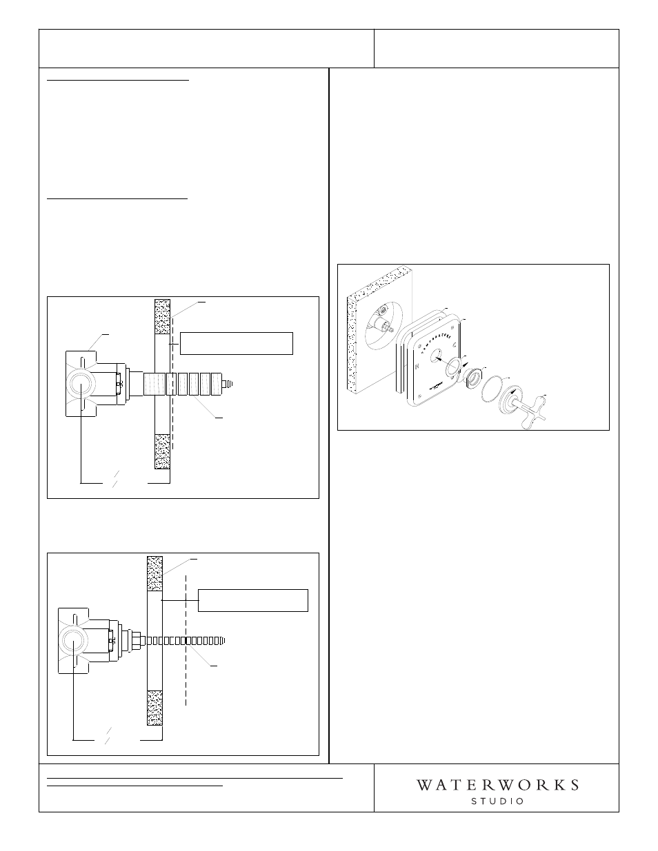
TRIM PLATE INSTALLATION:
8. Re-install the THREADED TUBE and make a mark on
the tube that is 1/8" in front of the finished wall.
9. Remove the tube then cut the tube at the mark
made in Step 8. DO NOT cut the end of the tube
with the internal threads. See Figure 3.
Figure 3
THREADED TUBE
FINISHED WALL
3
1
4
"MIN
4
1
4
"MAX
ROUGH IN
CUT TUBE 1/8" IN FRONT
OF THE FINISHED WALL
VALVE
10. Mark and then cut the CARTRIDGE STEM 1" in front
of the finished wall. See Figure 4.
Figure 4
CARTRIDGE STEM
FINISHED WALL
3
1
4
"MIN
4
1
4
"MAX
ROUGH IN
CUT STEM 1" IN FRONT
OF THE FINISHED WALL
¾ See Figure 5. for Steps 11-13.
11. Re-install the cut THREADED TUBE onto the VALVE.
12. Hold the TRIM PLATE against the finished wall,
making sure FOAM GASKET is touching the wall.
Thread and tighten the TRIM CONNECTOR onto the
threaded tube, making sure the RED FIBER
WASHER is between the trim connector and trim
plate.
13. With the correct orientation, thread the HANDLE
ASSEMBLY onto the TRIM CONNECTOR making
sure the O-RING is between the escutcheon and
TRIM PLATE. Note: The escutcheon is used to
tighten handle assembly.
Figure 5
FOAM GASKET
TRIM PLATE
RED FIBER WASHER
TRIM ADAPTER
O-RING
HANDLE
ASSEMBLY
¾ NOTE: The screws on the front of the trim plate are
aesthetic only and do not serve any mechanical
purpose and should not be removed.
¾ If further assistance is required, please contact
Product Support at 1-800-927-2120 (8am-6pm EST).
¾ See service part document for parts ordering,
available on WATERWORKS.COM.