Installation guidelines – Waterworks Henry Thermostatic with Shutoff Trim User Manual
Page 2
PRODUCT SUPPORT 800.927.2120 8am - 6pm EST
HENRY
Thermostatic with Shutoff Trims
INSTALLATION GUIDELINES
Page 2 of 3
11.14.2012
These guidelines have been prepared for the professional contractor to aid in the installation of:
HENRY METAL LEVER HANDLE WITH THERMOSTATIC WITH METAL CROSS HANDLE SHUTOFF
TRIMS (STYLE# HNTH30)
All dimensions are based on original specification and are subject to change and variation.
Please consult your Design Associate for current specifications.
SEE SERVICE PART DOCUMENT FOR PART ORDERING, AVAILABLE ON WATERWORKS.COM
3. Hold the back plate up to the finished wall and slide
the thermo trim plate over the all thread tube. Make
sure the thermo trim plate is centered on the back
plate and the threaded sleeves on the shut-off
valves pass through the holes on the back plate.
¾
See Figure - 02 for steps 4 - 8
4. While holding the back plate and thermo trim plate
against the finished wall, mark the all thread tube at
a point 3/16" beyond where it protrudes from the
trim plate. Make a mark on the threaded sleeves that
is 1/2" from the front face of the back plate.
5. Remove the threaded sleeves from the shut-off
valves and make marks on the splined stems that are
1-3/8" from the front face of the back plate.
6. Remove the trim plate, the back plate, the all thread
tube and the threaded sleeves from the valve. Cut
the all thread tube and threaded sleeves at the
marks made in Step 4. DO NOT cut the ends that
have the internal threads.
7. Cut the splined stems at the marks made in Step 5.
8. Re-attach the all thread tube and threaded sleeves
then hold the back plate against the finished wall
and slide the trim plate is centered and fits properly
into the opening in the back plate.
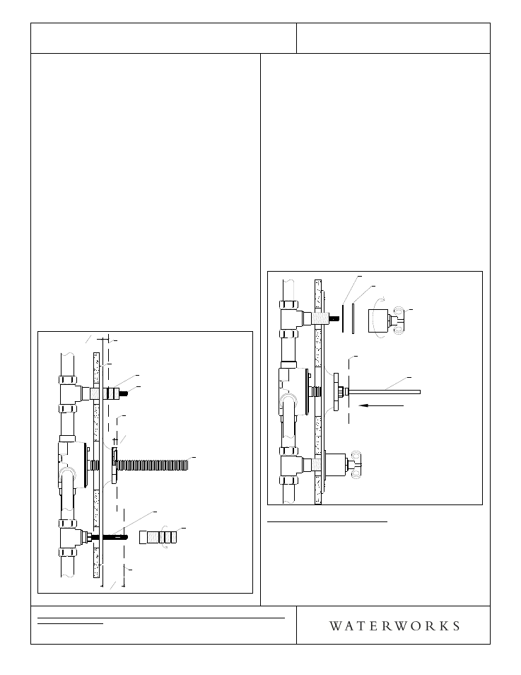
Figure - 02
Cut Plane
For All Thread Tube
1 3 8"
Cut Plane
For Splined Stem
Threaded
Sleeve
Spline Stem
Spline Stem
Threaded Sleeve
Face of Back Plate
Cut Plane
For Threaded Sleeve
All Thread
Tube
3
16"
1
2"
¾
See Figure - 03 for steps 9 - 12
9. Tightly thread the trim nut onto the all thread tube.
This will hold the trim plate to the back plate against
the wall.
10. Slide the escutcheons, with rubber washers behind
them, over the 2 cut threaded sleeves. Tighten the
shut-off handle assemblies on the threaded sleeves,
making sure the escutcheon is centered and the
handle is in the correct orientation.
11. Fully insert the square tube into the trim nut, then
by feel, make sure it slides over the stem and stops
against the valve cover plate. When seated properly
onto the stem, the square tube will have rotational
resistance.
12. Mark the square tube at the point where it passes
through the face of the trim nut. Remove the square
tube and cut it 1/8" behind the mark that was just
made. Re-insert the tube back into the trim nut
making sure it is slightly recessed into the nut.
Figure - 03
Mark Plane
For Square Tube
Square Tube
Shut off
Handle Assembly
Escutcheon
Rubber Washer
TEMPERATURE CALIBRATION:
¾
See Figure - 04 for Steps 13 - 17
¾
The risk of scalding exists until the installer has
properly calibrated the temperature setting.
13. Turn on the water supply and one of the shut-off
valves to run water through the valve and insert a
bladed screw driver into the square tube.