Waterworks Henry Thermostatic with Shutoff Trim User Manual
Installation guidelines
PRODUCT SUPPORT 800.927.2120 8am - 6pm EST
HENRY
Thermostatic with Shutoff Trims
INSTALLATION GUIDELINES
Page 1 of 3
11.14.2012
These guidelines have been prepared for the professional contractor to aid in the installation of:
HENRY METAL LEVER HANDLE WITH THERMOSTATIC WITH METAL CROSS HANDLE SHUTOFF
TRIMS (STYLE# HNTH30)
All dimensions are based on original specification and are subject to change and variation.
Please consult your Design Associate for current specifications.
SEE SERVICE PART DOCUMENT FOR PART ORDERING, AVAILABLE ON WATERWORKS.COM
Metal Lever Handle Thermostatic with Metal Cross
Handle Shutoff Trims
Style No. HNTH30
Code No. HNSV30
SPECIFICATIONS:
Control Valve Rough-In Depth: 2-1/8" MIN - 3-1/8" MAX
Hot Limit Safety Stop: Yes
REQUIRED PLUMBING DETAILS:
Henry Thermostatic Valve
STYLE No. GUTH47
CODE No. GUSV47R
IMPORTANT:
¾
To ensure this product is installed properly, you
must read and follow these guidelines.
¾
The owner/user of this product must keep this
information for future reference.
¾
This product is intended to work with the Henry
Thermostatic Valve which features anti-scald
protection. The risk of scalding exists until the
installer has properly calibrated/adjusted the
temperature setting during final trim installation.
¾
Be sure your installation conforms to federal state,
and local codes. In the State of Massachusetts, all
installations must comply with the rules and
regulations set forth within 248 CMR.
¾
This product must be installed by a professional
licensed contractor and must be onsite prior to
rough-in, this allows the installer to visualize the
installation.
¾
This product and the required valve (GUTH47)
CANNOT be installed horizontally. This product
must be installed with all the handles aligned
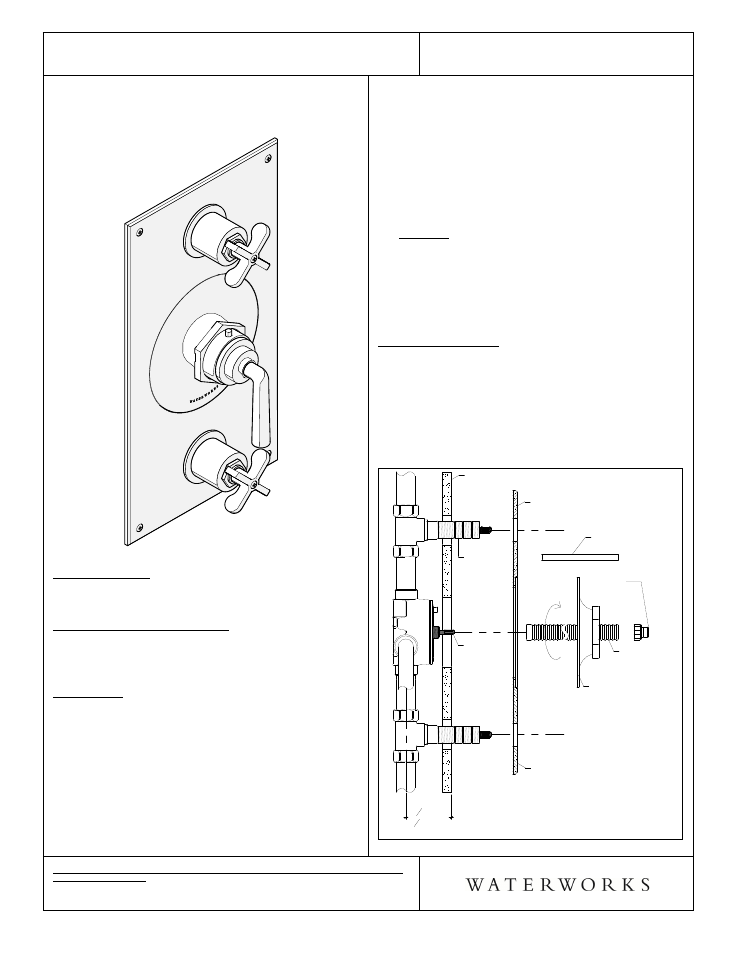
vertically as shown in the image to the left.
¾
Use only a strap wrench or protected/smooth-jaw
wrench on any finished surface.
¾
DO NOT use putty on fittings.
TRIM INSTALLATION :
¾
See Figure - 01 for steps 1 & 2
1.
Remove the tile guards from the valve.
2. Unthread the trim nut adapter from the all thread
tube, remove the square tube, then thread the all
thread tube onto the cartridge stem.
Figure - 01
2
1
8
"MIN
3
1
8
"MAX
ROUGH-IN
Screws on back plate
are aesthetic only
Cartridge
Stem
Threaded
Sleeve
Back Plate
Finished Wall
All Thread
Tube
Square Tube
Trim Nut
Adapter
Thermo Trim
Plate