Installation guidelines – Waterworks Easton Classic Pressure Balance with Diverter Trim with Oak Lever Handles User Manual
Page 2
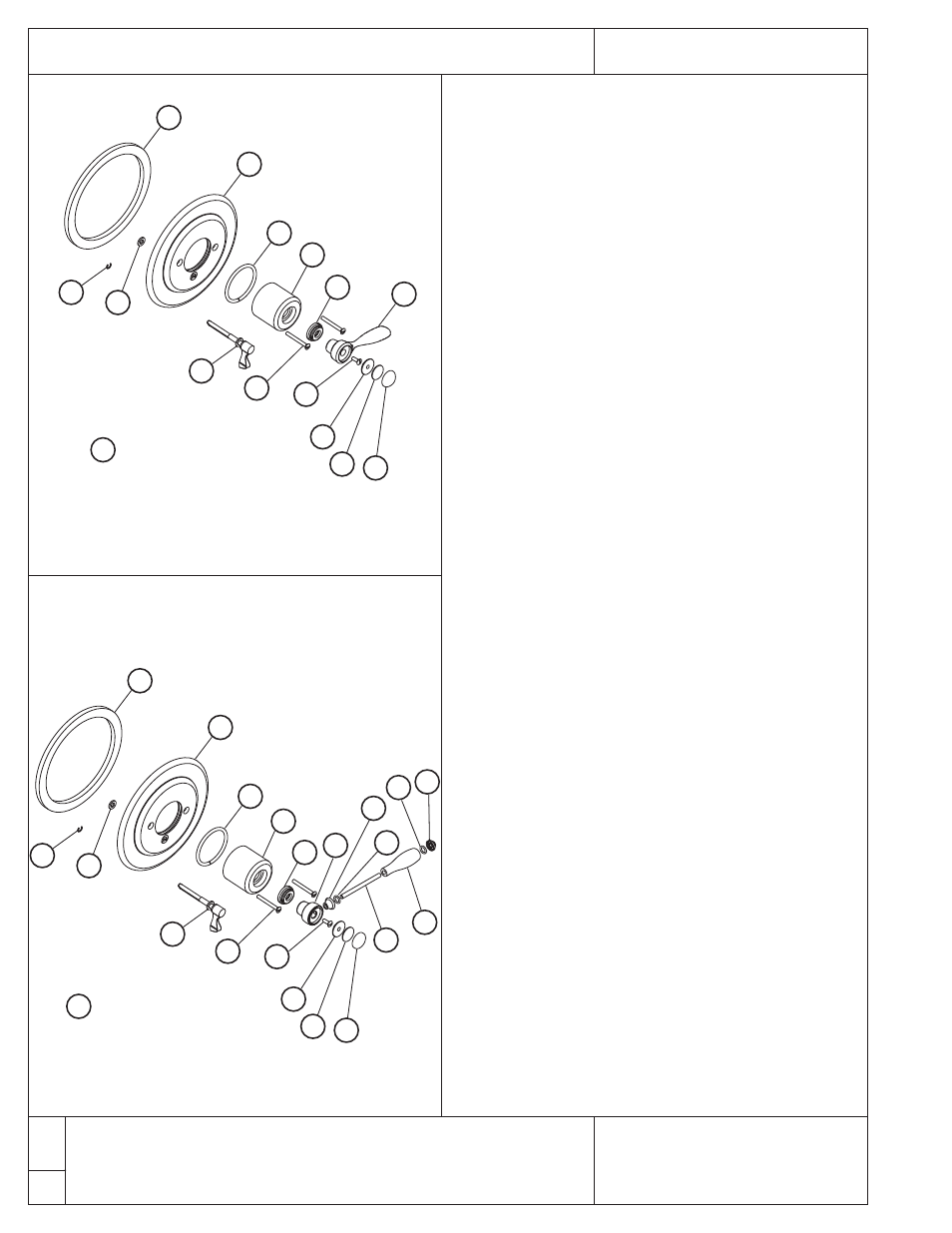
Easton
®
Pressure Balance With Diver ter
Installation Guidelines
W A T E R W O R K S
®
10
11
12
13
14
7
6
2
1
5
3
4
9 x2
12
: Threaded
8
11
12
13
14
10
10a
10b
10c
10d
10e 10f
7
6
2
1
5
3
4
9 x2
12
: Threaded
8
EASV92-K (metal lever handle trim)
EASV93-K (white porcelain lever handle trim)
EASV94-K (black porcelain lever handle trim)
EASV95-K (oak lever handle trim)
8. Allow the valve to run in warm position for a few minutes to
completely flush the system. If system is quite dirty, remove
valve spindle to ensure proper flushing.
9. IMPORTANT: This valve is equipped with a limit stop screw(T-
34) to be used to limit the valve handle from being turned to
excessively hot water discharge temperatures.
10. Setting the limit stop screw: Open the valve to the maximum
desired temperature then turn the limit stop screw(T-34) in until
it seats.
11. WARNING: FAILURE TO ADJUST THE LIMIT STOP SCREW
PROPERLY MAY RESULT IN SERIOUS SCALDING.
12.. WARNING: THIS SHOWER SYSTEM MAY NOT PROTECT
THE USER FROM SCALDING WHEN THERE IS A FAILURE
OF OTHER TEMPERATURE CONTROLING DEVISES
ELSEWHERE IN THE PLUMBING SYSTEM.
INSTALL THE TRIM:
13. Slide the trim plate assembly(1-6) over the valve stem while
making sure the diverter shaft/handle(3,4,5) are aligned with the
diverter spindle(T-23A,B). IMPORTANT: T-23A,B must be
properly aligned and the handle must rest at 6 o-clock position.
If the handle and diverter spindle are not properly aligned, the
valve will not function. See Figure 1.
14. Secure the plate against the wall using the screws(9) provided.
If desired, a bead of clear silicone can be applied to the back side
of the trim plate(2).
15. Apply a small mount of lubricant to the o-ring(6) then hand
tighten the dome cover(7) completely down onto the
spindle(TA-10). The dome cover MUST be tightened to prevent
damage to the handle.
16. Slide the handle trim spacer(8) onto the valve stem then attach
the handle using the handle screw provided(11).
17.Thread the index retainer(12) into the handle then attach the
index(14) to the retainer using the adhesive pad(13).
18. Open the valve and confirm the temperature setting, adjust as
required. Verify that the diverter is functioning properly.
➢ If further assistance is required, please contact Product Support
at 1-800-927-2120 (8am-7pm EST).
3/05
These guidelines have been prepared for the professional contractor to aid in the installation of:
PRESSURE BALANCE WITH DIVERTER (
EASV92-K & GUSV86R
) (
EASV93-K &
GUSV86R
) (
EASV94-K & GUSV86R
) (
EASV95-K & GUSV86R
)
All dimensions are based on original specifications and are subject to change and variation.
Please consult your Design Associate for current specifications.