Installation guidelines – Waterworks Regulator Gooseneck Double Spout Marquee Kitchen Faucet, Metal Wheel Handles and Spray User Manual
Page 2
PRODUCT SUPPORT 800.927.2120 8am - 6pm EST
REGULATOR
Gooseneck Double Spout Marquee Kitchen Faucet
Installation Guidelines
Page 2 of 5
Rev - 01
10.9.2014
These guidelines have been prepared for the professional contractor to aid in the installation of:
REGULATOR GOOSENECK DOUBLE SPOUT MARQUEE KITCHEN FAUCET WITH METAL WHEEL HANDLES AND
SPRAY (STYLE No. RGKM50, RG50KM UK)
All dimensions are based on original specification and are subject to change and variation.
Please consult your Design Associate for current specifications.
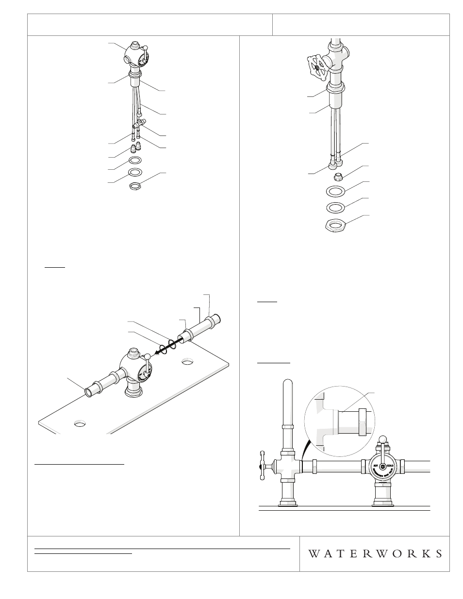
FIGURE – 02
5. Insert the TUBES into the TEMPRATURE VALVE BODY,
making sure the O-RINGS, METAL WASHERS, and
NUTS are attached properly. Do
NOT tighten the
NUTS. The flanged end of the TUBES must be on the
outside. See FIGURE – 03.
NOTE: The TUBES are aesthetic only and do NOT hold
or carry water. The TUBES can be cut to accommodate
different on-center spreads. The max on-center spread
for each TUBE is 12” [305mm].
FIGURE - 03
SPOUT(S) INSTALLATION:
Each SPOUT works independently from the other and
each has a volume/on/off control function.
The LEFT SPOUT will have one of the HOSES plugged
as shown in FIGURE – 04.
6. Remove the NUT, METAL WASHER, and RUBBER
WASHER from the SHANK. See FIGURE - 04. Do
NOT
remove the O-RING beneath the ESCUTCHEON.
NUT
HOSE "RED"
SHANK
METAL WASHER
RUBBER WASHER
HOUSING
HOSE "BLUE"
TEE
HOSE "GREEN"
ESCUTCHEON
VALVE BODY
NUT
HOSE "RED"
SHANK
METAL WASHER
RUBBER WASHER
HOUSING
HOSE "BLUE"
TEE
HOSE "GREEN"
ESCUTCHEON
VALVE BODY
NUT
TUBE
NUT
METAL WASHER
O-RING
"FLANGED END
DO NOT CUT"
NUT
TUBE
NUT
METAL WASHER
O-RING
"FLANGED END
DO NOT CUT"
FIGURE - 04
7. Ensure that the HOSES are securely tightened to the
SPOUT, then insert the SHANK through the Ø1-3/4”
[44mm] or left hole on the mounting surface making
sure the O-RING is beneath the ESCUTCHEON.
NOTE: The HOSES are marked with colored ZIP TIES
to identify their function.
Green for incoming mixed
water and
yellow for outgoing diverted water.
8. Ensure that the flanged end of the TUBE sits flush
with the SPOUT VALVE BODY. See FIGURE - 05.
Thread and tighten the both NUTS on the TUBE.
CAUTION
: The TUBES can be cut if necessary, adjust
as needed.
Do NOT cut the flanged end.
FIGURE - 05
NUT
METAL WASHER
RUBBER WASHER
PLUG
HOSE "YELLOW"
HOSE "GREEN"
SHANK
ESCUTCHEON
NUT
METAL WASHER
RUBBER WASHER
PLUG
HOSE "YELLOW"
HOSE "GREEN"
SHANK
ESCUTCHEON
FLANGE OF TUBE
AND SPOUT
VALVE BODY
MUST BE FLUSH
FLANGE OF TUBE
AND SPOUT
VALVE BODY
MUST BE FLUSH