Installation guidelines – Waterworks .25 One Hole High Profile Kitchen Faucet, Metal Handle and Metal Spray User Manual
Page 2
PRODUCT SUPPORT 800.927.2120 8am - 6pm EST
.25
One Hole High Profile Kitchen Faucet with Lever Handle and Spray
Installation Guidelines
Page 2 of 3
Rev - 01
10.31.2014
These guidelines have been prepared for the professional contractor to aid in the installation of:
.25 ONE HOLE HIGH PROFILE KITCHEN FAUCET WITH METAL LEVER HANDLE AND METAL SPRAY
(STYLE No. PTKM10, PT10KM UK).
All dimensions are based on original specification and are subject to change and variation.
Please consult your Design Associate for current specifications.
2. Insert the SPOUT SHANK through the hole on the
mounting surface making sure the RUBBER WASHER is
beneath the ESCUTHCEON.
3. Re-install the RUBBER WASHER, METAL WASHER and
MOUNTING NUT. Securely tighten the MOUNTING NUT
to secure the SPOUT to the mounting surface.
4. Re-attach the HOSES to the EXTENSION TUBES and
securely tighten.
5. Connect the ADAPTERS from the HOSES to the water
supplies making sure the O-RINGS are inside the
ADAPTERS. See FIGURE – 02.
FIGURE - 02
6. Connect the HOSES to the ADAPTERS making sure
they are not pinched or kinked.
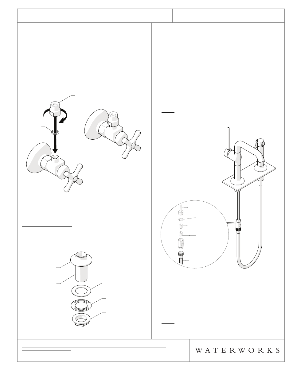
SPRAY INSTALLATION:
7. Remove the MOUNTING NUT, METAL WASHER, and
RUBBER WASHER from the SHANK. Do
NOT remove
the RUBBER WASHER beneath the ESCUTCHEON.
FIGURE - 03
O-RING
ADAPTER
O-RING
ADAPTER
MOUNTING NUT
METAL WASHER
RUBBER WASHER
SHANK
ESCUTCHEON
MOUNTING NUT
METAL WASHER
RUBBER WASHER
SHANK
ESCUTCHEON
8. Insert the SHANK through the hole on the mounting
surface making sure the RUBBER WASHER is beneath
the ESCUTCHEON.
9. Re-install the RUBBER WASHER, METAL WASHER and
MOUNTING NUT. Securely tighten the MOUNTING NUT
to secure the SHANK to the mounting surface.
10. Connect the conical end of SPRAY HOSE to the
SPRAY, then insert the knurled end of the SPRAY
HOSE through the SHANK and place the SPRAY inside
the ESCUTCHEON.
11. Connect the SPRAY HOSE to the CHECK VALVE
HOUSING attached to the OUTLET TUBE on the
SPOUT. See FIGURE – 04.
NOTE: The CHECK VALVE HOUSING contains 2
CHECK VALVES. One of the CHECK VALVES is flow
regulated at 2.2gpm. The other is
NOT flow regulated.
FIGURE - 04
FINISH AND INSPECT THE INSTALLATION:
12. Remove the AERATOR from the SPOUT using the
TOOL provided then open the hot and cold supplies
and carefully operate the HANDLE to flush out any
debris in the supply lines.
NOTE: Flush out the supply lines prior to operating the
SPRAY.
CHECK VALVE
FLOW
REGULATING
CHECK VALVE
HOUSING
SPRAY
HOSE
RUBBER
WASHER
OUTLET
TUBE
CHECK VALVE
FLOW
REGULATING
CHECK VALVE
HOUSING
SPRAY
HOSE
RUBBER
WASHER
OUTLET
TUBE