4 wiring – Pilz PSEN op4B-S-3-080 User Manual
Page 24
PSEN op4B Series
Operating Manual
20
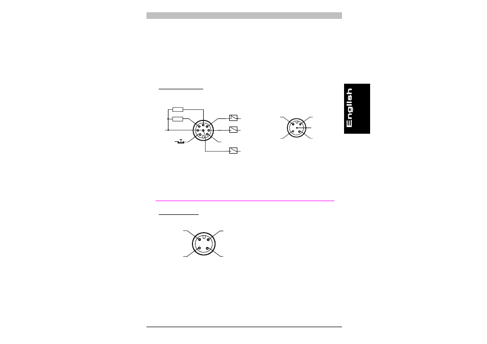
4 WIRING
4.1 Electrical connections
The electrical connections of the emitter (TX) and receiver (RX) are
made via M12 connectors, which are located on the bottom of both
units.
RECEIVER (RX):
8-pin M12 connector
2
8
1
5
3
4
7
6
+24 Vdc
0 V
OSSD1 PNP
OSSD2 PNP
+24 Vdc
+24 Vdc
Feedback
loop
+24 Vdc
External N.C. contact
OVR1
0 V
Externer N.O. contact
OVR2
External N.O. contact
3
4
2
1
MUTING2
0 V
+24 Vdc
MUTING1
not connected
1 = white
= TEST/START
2 = brown
= +24
Vdc
3 = green
= OVERRIDE
1
4 = yellow
= Feedback loop
5 = grey
= OSSD1
6 = pink
= OSSD2
7 = blue
= 0V
8 = red
= OVERRIDE
2
1 = brown
= +24
Vdc
2 = white
= MUTING
2
3 = blue
= 0V
4 = black
= MUTING
1
5 = grey
= Not
connected
EMITTER (TX):
4-pin M12 connector
3
4
2
1
not connected
0 V
+24 Vdc
not connected
1 = brown = +24 Vdc
2 = white = Not connected
3 = blue = 0 V
4 = black = Not connected