Pilz PSEN op4B-S-3-080 User Manual
Page 21
Operating Manual
PSEN op4B Series
17
3 MECHANICAL ASSEMBLY
The emitter (TX) and receiver (RX)
must be assembled so that the
respective optical surfaces are aligned
in parallel and the connectors are
positioned on the same side. The
distance between the emitter (TX) and
receiver (RX) must be within the
operating range of the model you are
using (see type label or Chapter 9,
“Technical details”).
Align the devices precisely, following the guidelines given in Chapter 5,
“Alignment”.
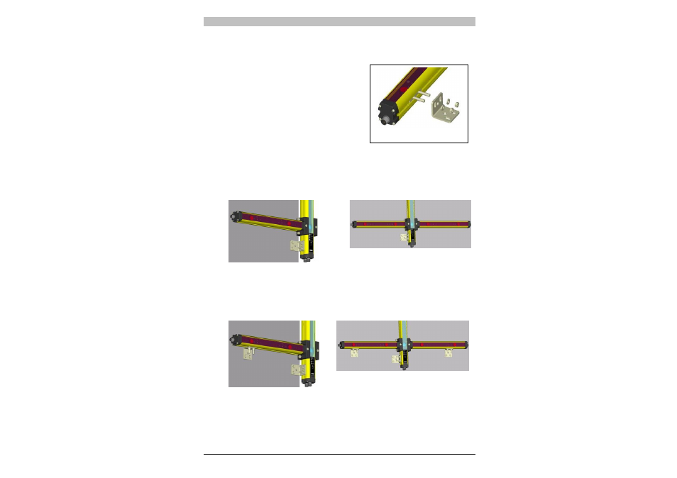
Depending on the application, both units may either be screwed on
using the fixing bolts supplied or by using a rigid mounting bracket.
Fig. 12
Where there is particularly strong vibration, the muting sensor profiles
will also need to be screwed on using rigid mounting brackets (Fig.
13).
Fig. 13
Fig.11