2 airflow paths, Airflow paths, Am4024(e) airflow impedance by zone [n/m – Kontron AM4024e User Manual
Page 57: Am4024(e) airflow impedance by zone [inches h2o, Thermal zones of the am4024(e) module
D R A F T — F O R I N
T E R N A L U S E O N L Y
57
www.kontron.com
User Guide
AM4024(E)
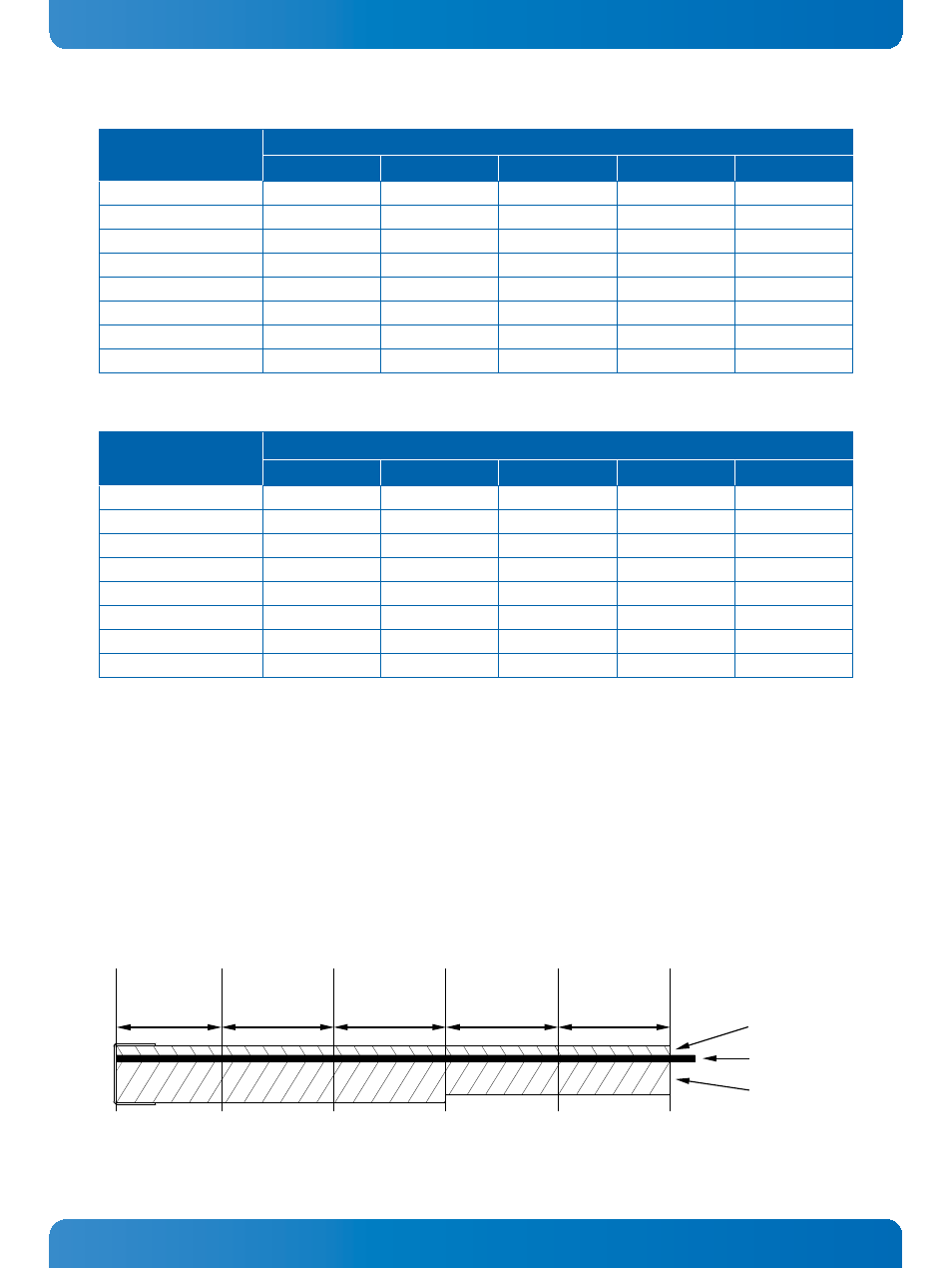
5.1.2 Airflow Paths
The area between the front panel and the AMC Card-edge connector is divided into five zones, one I/O
zone and four uniform thermal zones, A, B, C, and D. The PICMG AMC.0 Specification states that the
uniformity of the airflow paths’ resistance should provide an impedance on the A, B, C, and D zones
that is within ± 25% of the average value of the four thermal zones.
The following figure shows the thermal zones of the AM4024(E).
Figure 15: Thermal Zones of the AM4024(E) Module
Table 38: AM4024(E) Airflow Impedance by Zone [N/m²]
VOLUMETRIC
FLOW RATE [CFM]
PRESSURE DROP [N/m²]
I/O ZONE
ZONE A
ZONE B
ZONE C
ZONE D
5
3.5 3.4 3.4
3.2 2.8
10
9.5 9.0 8.9
8.3 7.2
15
15.7 14.9 14.6 13.8 11.9
20
24.7
22.7
22.4 21.0 18.0
25
34.5 31.2 30.8
29.3
25.2
30
46.4 42.4
41.4 39.1 33.7
35
60.4 54.1 53.1 50.4 42.8
40
75.2 67.2
65.8 62.5 53.1
Table 39: AM4024(E) Airflow Impedance by Zone [inches H
2
O]
VOLUMETRIC
FLOW RATE [CFM]
PRESSURE DROP [inches H
2
O]
I/O ZONE
ZONE A
ZONE B
ZONE C
ZONE D
5
0.01
0.01
0.01
0.01
0.01
10
0.04
0.04
0.04
0.03
0.03
15
0.06
0.06
0.06
0.06
0.05
20
0.10
0.09
0.09
0.08
0.07
25
0.14
0.13
0.12
0.12
0.10
30
0.19
0.17
0.17
0.16
0.14
35
0.24
0.22
0.21
0.20
0.17
40
0.30
0.27
0.26
0.25
0.21
I/O ZONE
ZONE A
ZONE B
ZONE C
ZONE D
32.8 mm
34 mm
34 mm
34 mm
34 mm
PCB
component
envelope
component
envelope