4 power considerations, 1 am4024(e) voltage ranges, 2 carrier power requirements – Kontron AM4024e User Manual
Page 49: 1 module management power, 2 payload power, Power considerations, Am4024(e) voltage ranges, Carrier power requirements, Module management power, Payload power
D R A F T — F O R I N
T E R N A L U S E O N L Y
49
www.kontron.com
User Guide
AM4024(E)
4 Power Considerations
4.1 AM4024(E) Voltage Ranges
The AM4024(E) has been designed for optimal power input and distribution. Still it is necessary to ob-
serve certain criteria essential for application stability and reliability.
The AM4024(E) requires two power sources, the module management power for the MMC (nominal:
3.3V DC) and a single payload power (nominal: 12V DC) for the module components.
The following table specifies the ranges for the input power voltage within which the board is functional.
Note:
Failure to comply with the instructions above may result in damage to the board or improp-
er operation.
4.2 Carr ier Power Requirements
4.2.1 Module Management Power
The module management power is used only for the Module Management Controller (MMC), which has
a very low power consumption. The management power voltage measured on the AMC at the connector
shall be 3.3 V ± 5% and the maximum current is 150 mA (see Table 34, DC Operational Input Voltage
Ranges).
The module management power is below 0.45 W and it has therefore not been taken into consideration
during the measurements.
4.2.2 Payload Power
Payload power is the power provided to the module from the carrier or the backplane for the main func-
tion of the module. The payload power voltage should be selected at the higher end of the specified
voltage range. The maximum continuous current limit value is based on the AMC module's power limit
of 80 W. At the minimum supply voltage of 10.8 V, the 80 W requires approximately 7.4 A.
The payload power voltage shall be at least 10.8 V and not more than 13.2 V at the module contacts
during normal conditions under all loads (see Table 34, DC Operational Input Voltage Ranges). The
bandwidth-limited periodic noise due to switching power supplies or any other source shall not exceed
200 mV peak to peak.
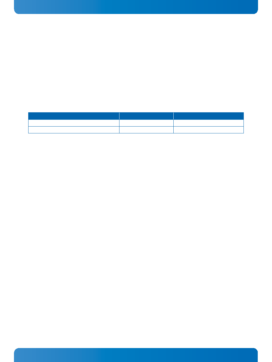
Table 34: DC Operational Input Voltage Range
INPUT SUPPLY VOLTAGE
OPERATING RANGE
OPERATING RANGE
Payload Power (nominal: 12V DC)
10.0 V min. to 14.0 V max.
10.8 V min. to 13.2 V max.
Module Management Power (nominal: 3.3V DC)
3.0 V min. to 3.6 V. max.
3.135 V min. to 3.465 V max. (±5%)