6 board id low-byte register (bidl), 7 led configuration register (lcfg), Board id low-byte register (bidl) – Kontron AM4024e User Manual
Page 46: Led configuration register (lcfg)
D R A F T — F O R I N
T E R N A L U S E O N L Y
46
www.kontron.com
User Guide
AM4024(E)
3.3.6 Board ID Low-Byte Register (BIDL)
3.3.7 LED Configuration Register (LCFG)
The LED Configuration Register holds a series of bits defining the onboard configuration for the front
panel User-Specific LEDs.
Regardless of the selected configuration, the User-Specific LEDs are used to signal a number of fatal
onboard hardware errors, such as:
ULED3:
Power failure (red)
ULED2:
Clock failure (red)
ULED1:
Hardware reset (red)
ULED0:
uEFI BIOS boot failure (red)
In POST mode, the ULED3..0 fulfill a basic debug function during the boot-up phase as long as the first
access to Port 80 is processed. For further information on reading the 8-bit uEFI BIOS POST Code, refer
to Chapter 2.7.1.2, User-Specific LEDs.
In Mode A, the ULEDs can be individually configured according to the application requirements (see
Chapter 3.3.8, LED Control Register).
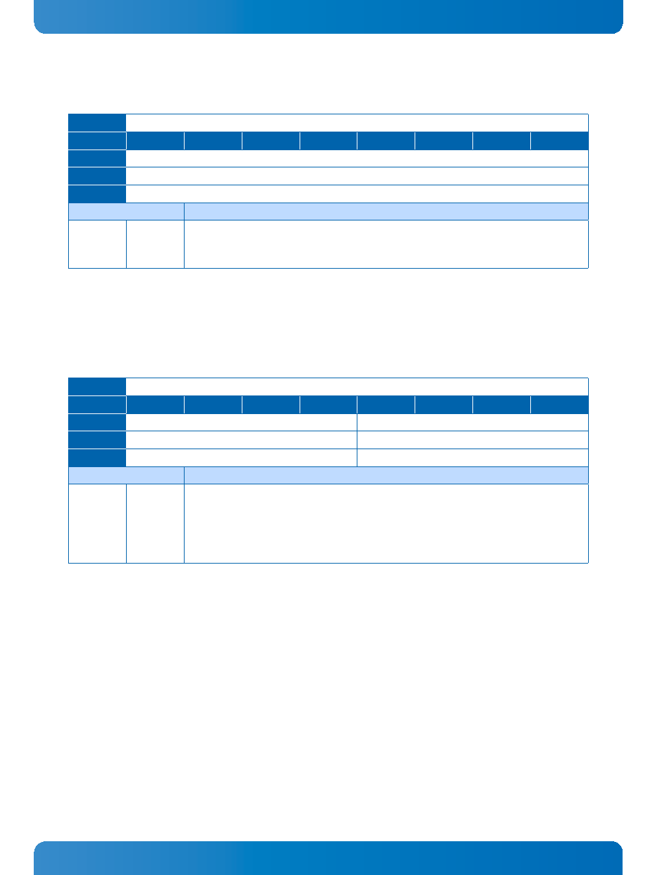
Table 30: Board ID Low-Byte Register (BIDL)
ADDRESS
0x28D
BIT
7
6
5
4
3
2
1
0
NAME
BIDL
ACCESS
R
RESET
0x10 (AM4024) / 0x12 (AM4024E)
BITFIELD
DESCRIPTION
7
BIDL
Board identification:
AM4024:
0xB410
AM4024E:
0xB412
Table 31: LED Configuration Register (LCFG)
ADDRESS
0x290
BIT
7
6
5
4
3
2
1
0
NAME
Reserved
LCON
ACCESS
R
R/W
RESET
0000
0000
BITFIELD
DESCRIPTION
3..0
LCON
User-Specific LED Configuration:
0000 = POST (ULEDs build a binary vector to display Port 80 signals)
0001 = Mode A (LEDs are controlled via the LCTRL register)
0010 = Mode B (default mode, function after boot-up)
0011 - 1111 = Reserved