14 power supply, 1 connector, 2 power front panel header – Kontron pITX-SP User Manual
Page 35: Pitx-sp user's guide
KTD-S0002-I
Page 30
Power Supply
p
ITX-SP User's Guide
14 Power Supply
The pITX-SP SBC has a power input voltage range from +4.75 to +5.25V DC. All other voltages are generated
onboard (e.g. +3.3V system and +1.8V memory voltage).
14.1 Connector
The power supply is injected through the connector J2300 (3 pins, DC power jacket 2.1mm).
Header
Pin
Signal Name
Function
1
VCC
1)
Power supply +5V
2
GND
Ground
1
3
GND
Ground
Note:
1)
To protect the external power lines of peripheral devices make sure that
- the wires have the right diameter to withstand the maximum available current.
- to enclosure of the peripheral device fulfills the fire-protecting conditions of IEC/EN 60950.
Warning: Don't overload the onboard system voltage +3.3V (microSD card socket, SDIO pin strip and Digital I/O connector). The
maximum current shouldn't exceed 250mA.
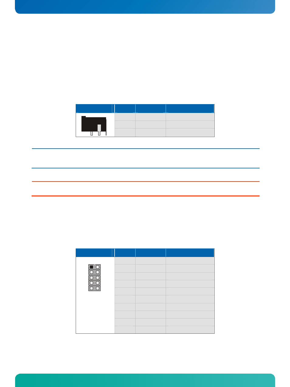
14.2 Power Front Panel Header
The power button and other power signals are available through the pin strip J1804 (10 pins). The harddisk
LED implies P-ATA and S-ATA.
Header
Pin
Signal Name
Function
1
RST_BTN+
Reset button (positive)
2
PWR_BTN+
Power button (positive)
3
RST_BTN-
Reset button (negative)
4
PWR_BTN-
Power button (negative)
5
HDD_LED-
Harddisk LED (negative)
6
RSVD
Reserved
7
HDD_LED+
Harddisk LED (positive)
8
RSVD
Reserved
9
RSVD
Reserved
1
2
9
10
10
RSVD
Reserved