8parallel-ata interface (p-ata), 1 connector, Pitx-sp user's guide – Kontron pITX-SP User Manual
Page 24
KTD-S0002-I
Page 19
Parallel-ATA Interface (P-ATA)
p
ITX-SP User's Guide
8
Parallel-ATA Interface (P-ATA)
The pITX-SP features one Parallel-ATA interface (up to UDMA5 mode) that can drive two harddisks. When
two devices share a single adapter they are connected in a master/slave, daisy-chain configuration. If only
one drive is connected you must set it as master.
8.1
Connector
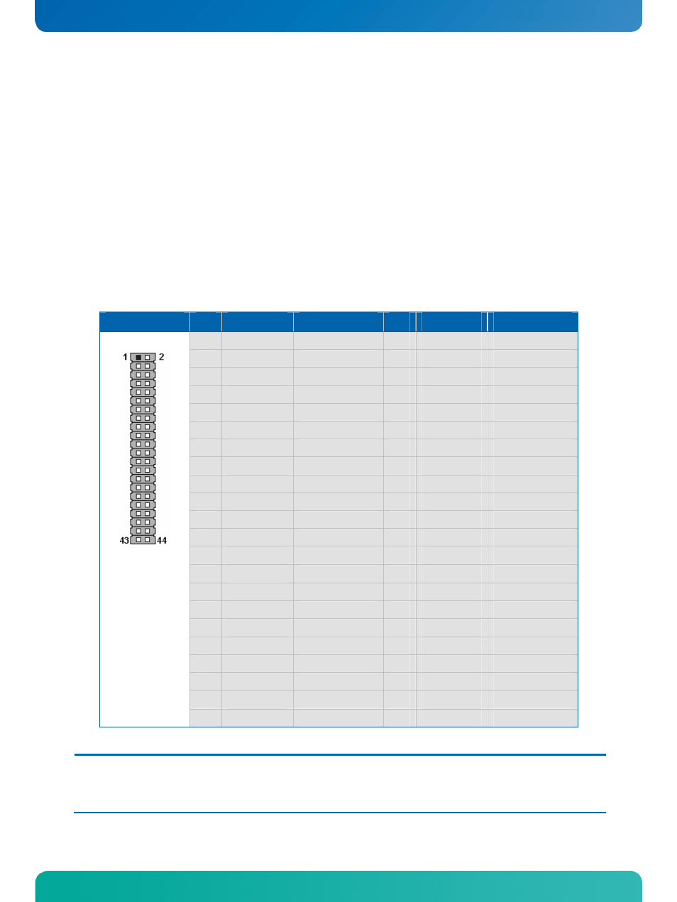
The P-ATA interface is available through connector J3400 (44 pins). This interface is designed in 2 mm grid
for optimal connectivity to a 2.5” harddisk.
You can use two cables to directly connect a harddisk in a 2.5” form factor (KAB-IDE-2MM, part number
96021-0000-00-0) or a 3.5” form factor (KAB-IDE-25, part number 96020-0000-00-0).
Header
Pin Signal Name
Function
Pin Signal Name
Function
1
/RESET
Reset
2
GND
Ground
3
D7
Data 7
4
D8
Data 8
5
D6
Data 6
6
D9
Data 9
7
D5
Data 5
8
D10
Data 10
9
D4
Data 4
10
D11
Data 11
11
D3
Data 3
12
D12
Data 12
13
D2
Data 2
14
D13
Data 13
15
D1
Data 1
16
D14
Data 14
17
D0
Data 0
18
D15
Data 15
19
GND
Ground
20
Key (N.C.)
Key pin
21
DRQ
DMA request
22
GND
Ground
23
/IOW
I/O write
24
GND
Ground
25
/IOR
I/O read
26
GND
Ground
27
IOCHRDY
I/O channel ready
28
CSEL
2)
Cable select
29
/DACK
DMA acknowledge
30
GND
Ground
31
IRQ
Interrupt request
32
N.C.
Not connected
33
SA1
Address 1
34
ATAD
UDMA detection
35
SA0
Address 0
36
SA2
Address 2
37
/CS1
Chip select 1
38
/CS3
Chip select 3
39
ACT
Drive activity
40
GND
Ground
41
VCC
1)
Power +5V
42
VCC
1)
Power +5V
43
GND
Ground
44
N.C.
Not connected
Note:
1)
To protect the external power lines of peripheral devices make sure that
- the wires have the right diameter to withstand the maximum available current.
- to enclosure of the peripheral device fulfills the fire-protecting conditions of IEC/EN 60950.
2)
Pin 28 is connected with 470
Ω
to Ground for cable select P-ATA devices.