Vmod-2/vmod-2d, Installation – Kontron VMOD-2D User Manual
Page 67
VMOD-2/VMOD-2D
12/15/97
Installation
Page 4 - 7
Man. ID 03139, Rev. Index 0200
prehensive, and relies upon the user feed-back to make us aware of any such experiences.
Please also see similar table in the respective piggyback user's manual.
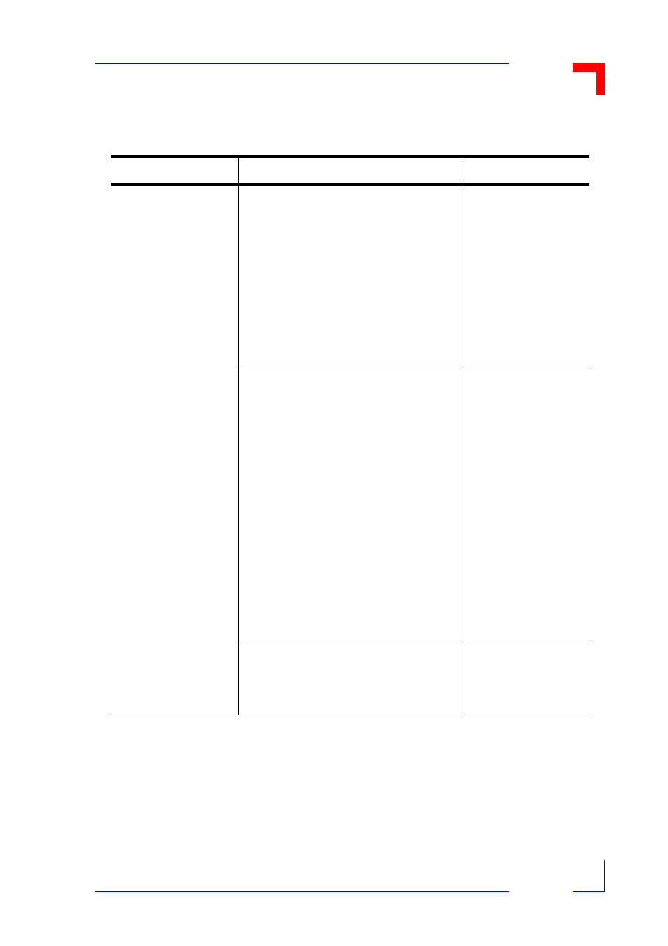
Table 4-1: Indications on Trouble-Shooting
Problem
Possible Cause or Solution
Action
None of the exter-
nally connected
devices have correct
or expected function
with the VMOD-2's
outputs
The external interface connector con-
nects to the wrong half of the front
panel connector (i.e. pins 01 to 24
instead of pins 27 to 50 for upper piggy-
back position). Move piggyback to other
location if this appears to be the case,
and test from there before rewiring your
interface cable.
a) the flat ribbon cable is fitted wrong
way up into the IDC connector i.e Pin 1
is connected to wire #50, etc.
See Sect. 2.4.3 for
precise front panel
pin-outs.
The piggyback has been accidently set
back one whole pin-row so only half it's
output connectors are connected to the
external interface and it's inputs are
misconnected to the VMOD's logic
interface/power.
a) The piggyback was displaced in the
BU1/0 and BU2 connectors by 180°
If you have made such a connection
then the VMOD-2 has been designed
that no damage to it or the piggyback
should occur. Move the piggyback for-
ward to the correct location and test for
correct function. If the piggyback or
VMOD-2 does become damaged
through misconnections of this kind, the
PEP warrantee is invalidated.
Check Physical con-
figuration.
Where opto-isolated piggybacks are
used, your external supply has failed or
has been turned off, gone into current
limit, or has had a fuse failure.
Check PSU
.