Vmod-2/vmod-2d, Functional description – Kontron VMOD-2D User Manual
Page 41
VMOD-2/VMOD-2D
12/15/97
Functional Description
Page 2 - 15
Man. ID 03139, Rev. Index 0200
Remember!
If any of the piggybacks you wish to use need any of the signals shown
bold/italic above (i.e. a 5230-xx type), a VMOD-2 set for an 8 KByte wide
address area must be used. Any piggyback not needing these additional
lines can be used on the VMOD-2 in either a 256 Byte or 8 KByte address
width setting.
2.5.2 VMOD-2 External Interface Connectors BU2a and BU2b
The twenty-six pin double row sockets are totally isolated from the remaining circuits of the
VMOD-2, and only connect the input/output side of the respective piggybacks 26-pin I/O
header directly to the upper or lower half of the 50-way VMOD-2 front panel connector.
The actual pins used are subject to the design of the piggyback, but the pin interconnections
between the two BU2 connectors and the 50-way front panel connector will always be the
same. To determine what pin-s your signals will appear on when using any ready made piggy-
back, please see the piggyback's user manual which will give precise details of the external
interfaces for use in both locations. If fault-tracing or designing your own piggybacks, the rela-
tionship of the respective piggyback locations (inputs/outputs) to the external connector is as
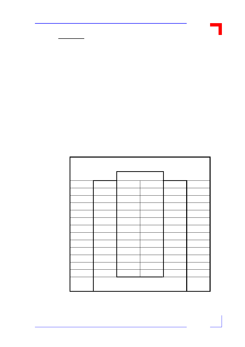
given in the table below.
Table 2-8: ST2/ST3 Connector Pin-Outs
VMOD-2 50-Way ST2/ST3 Pins as Used When a Selected Piggyback is
Fitted into the BU2 for Upper Location (A)
BU2 Pin #
50
24
2
1
24
50
47
21
4
3
22
48
45
19
6
5
20
46
43
17
8 7
18
44
41
15
10
9
16
42
39
13
12
11
14
40
37
11
14
13
12
38
35
9
16
15
10
36
33
7
18
17
8
34
31
5
20
19
6
32
29
3
22
21
4
30
27
1
24
23
2
28
49
23
26
25
23
49
VMOD-2 50-Way Pins Used When Piggyback is
Fitted into the BU2 for Lower Location (B)