Vmod-2/vmod-2d, Installation – Kontron VMOD-2D User Manual
Page 66
VMOD-2/VMOD-2D
12/15/97
Installation
Page 4 - 6
Man. ID 03139, Rev. Index 0200
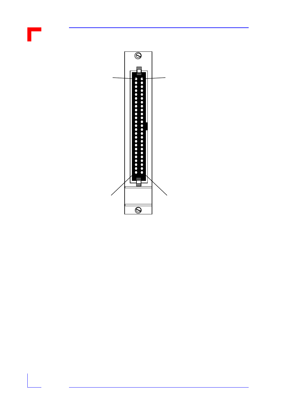
Figure 4-2: VMOD Standard front panel layout
The standard 3U high fascia may be replaced with a 6U (double height) front panel for use in
6U VMEbus systems. If making up your own double-height front panel, the VMOD must be so
placed that it uses the upper connector of any desired VMEbus slot. Alterantly a suitable 6U
fascia may be obtained from your local PepCard supplier, or even be specified for pre-assem-
bled 6U VMOD-2 and/or piggyback configurations during the initial ordering stage.
4.6 Trouble-Shooting for VMOD-2/VMOD and VMEbus System
This section is intended to assist users of the VMOD-2 and/or some of it's piggybacks to
quickly resolve any problems they may encounter in their application. It is by no means com-
VMOD
Odd pins
Pin 49
Pin 1
Eve n pins
Pin 50
Pin 2