Vmod-2/vmod-2d, Configuration, 1 jumper locations and functions – Kontron VMOD-2D User Manual
Page 59
VMOD-2/VMOD-2D
12/15/97
Configuration
Page 3 - 2
Man. ID 03139, Rev. Index 0200
3. Configuration
This section describes how to instal the VMOD-2's piggybacks, set the necessary jumpers,
and in general prepare the VMOD-2 for system operation. Before you proceed with this sec-
tion, please refer to the chosen piggybacks user's manuals, to see what restrictions or special
needs are to be taken into account, regarding their use with the VMOD/ VMOD-2 base mod-
ule.
3.1 Jumper locations and functions
The VMOD-2 possesses some twenty jumper selectable options, such as choice of physical
Address Block Size, Base Address, Address Modifiers, etc. These may be via simple "set" or
"open" two-pin jumpers, or through bridging two-pins of a three-pin jumper.
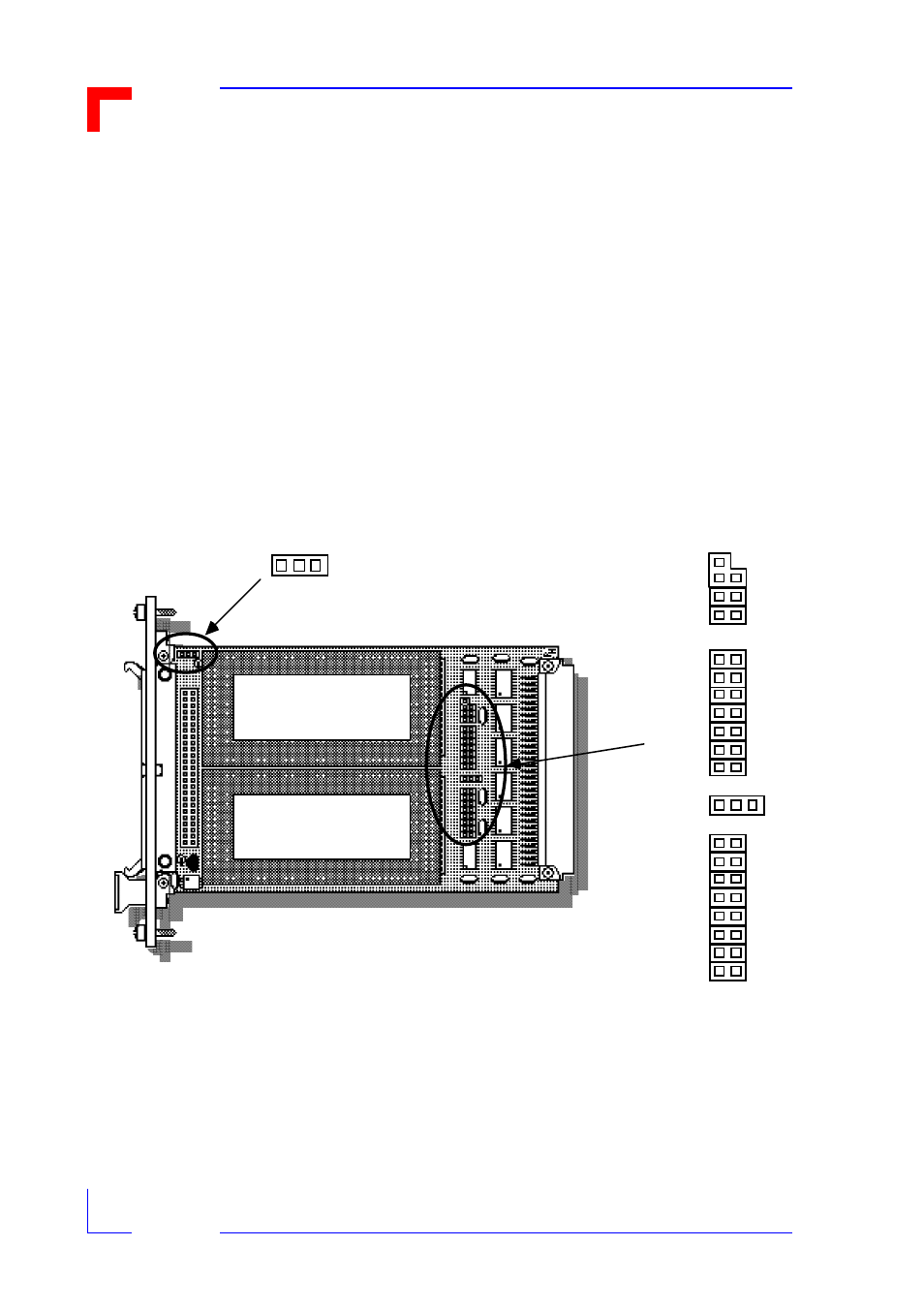
Figure 3-1 gives the VMOD-2's physical jumper locations, types and of especial importance
for the three-pin types the locations of the pin numbers which are used as setting references
throughout this chapter. Thereafter the jumpers are described individually in function order.
Figure 3-1: Jumper Locations Overview
The significance of the "2 1 3's" in the above figure is to define the pin setting choices which
these three pin jumpers offer e.g. jumper set onto pins 1-2 or onto 1-3. Pin 1 is always in the
middle of these three pin groups.
VMOD-2 is factory tested for full functionality, and is delivered in the configuration which best
suits the majority of users (default settings), see table 3-1 on the next page.
See piggyback A's
manual for details of
it's jumpers/s etting s
B20
B0 1
BO2
B0 3
B0 4
B0 5
B0 6
B0 7
B0 8
B0 9
B1 0
B1 1
B1 2
B1 3
B1 4
B1 5
B1 6
B1 7
B1 8
B19
2 - 1 - 3
3
1 2
2 - 1 - 3
See piggyback B's
manual for details of
it's jumpers/s etting s