Vmod-2/vmod-2d, Functional description – Kontron VMOD-2D User Manual
Page 32
VMOD-2/VMOD-2D
12/15/97
Functional Description
Page 2 - 6
Man. ID 03139, Rev. Index 0200
Int Fixed = Vector is pre-fixed on-board the piggyback
Int Progr = programmable vector on piggyback
2.2.4 Interrupt Vector Setting
As described before, the user can set his VMOD-2's Interrupt Vectors as appropriate to his
VMOD-2/Piggyback configurations needs. The selection of these vectors is subject to the
binary code of bits D0...D7 as derived by the setting of jumpers B11 to B4 respectively. B11 is
a three-pin type and can provide an identical or different vector for the two piggybacks. Three
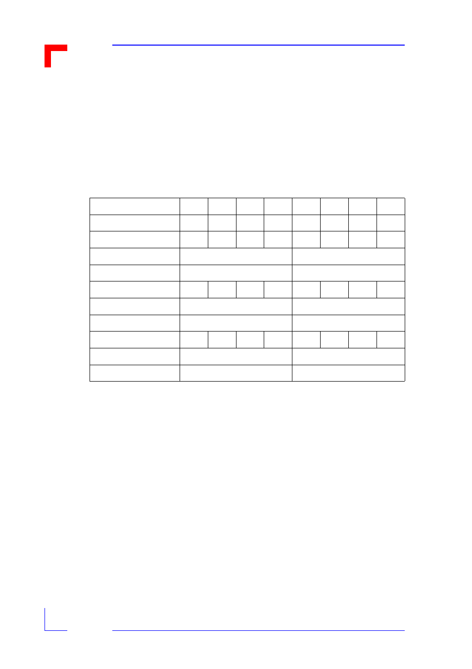
examples are given below where jumper B1 must be set to 1-2 to use these vectors.
* = If jumper B11 is set for 1-3, D0 will return a "0" for piggyback "A" and a "1" for
piggyback "B".
When jumper B11 is set to 1-2 the vector of both piggyback locations "A" and "B"
will be the same (so D0 = 0).
When jumper B11 is open the vector of both piggyback locations "A" and "B" will
also be the same (but D0 = 1).
Table 2-4: Interrupt Vector Selection
Interrupt Vector Bit
D7
D6
D5
D4
D3
D2
D1
D0
Jumper Numbers
B04
B05
B06
B07
B08
B09
B10
B11
Example Setting # 1
Open
Open
Open
Open
Set
Open
Set
1-3*
Upper PBs Vector
F
4
Lower PBs Vector
F
5
Example Setting # 2
Open
Open
Open
Open
Set
Open
Set
1-2*
Upper PBs Vector
F
4
Lower PBs Vector
F
4
Example Setting # 3
Open
Open
Open
Open
Set
Open
Set
Open
Upper PBs Vector
F
5
Lower PBs Vector
F
5