Vmod-2/vmod-2d, Configuration – Kontron VMOD-2D User Manual
Page 54
VMOD-2/VMOD-2D
12/15/97
Configuration
Page 3 - 7
Man. ID 03139, Rev. Index 0200
See also table 3-8 below for further interrupt vector setting information,
which may be helpful to you, in order to see how and when to use the
three-pin setting options of jumpers B1 and B11.
3.1.5 Using Interrupt Vector
Jumpers B4... B11 as described in the preceding section, provide a binary coded interrupt
vector, and may be freely programmed with each jumper representing an individual data bit,
B4 = MSB and B11 = LSB.
The table below will help you to decide when and how to use which settings, according to
what facilities your chosen piggybacks support.
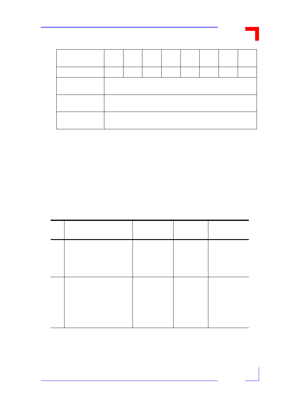
Table 3-7:
Interrupt Vector Selection (With Jumper B1 BeingCompletely Open)
Interrupt Vector
Bit
D7
D6
D5
D4
D3
D2
D1
D0
Jumper Numbers
B04
B05
B06
B07
B08
B09
B10
B11
Jumper Decod-
ing
May be any setting "Don't Care" since these settings are ignored
Upper PBs Vec-
tor
Derived from "intelligent" piggyback
Lower PBs Vec-
tor
Derived from "intelligent" piggyback
Table 3-8: Interrupt Vector Configuration Examples
#
Configuration
Vector Modes
B1 Settings
B4...B11
Settings
1)
Two piggybacks, both able
to generate interrupt vec-
tors are fitted to the VMOD-
2 and the user wants "intel-
ligent" vectors.
Use Piggyback
Generated
Vectors
Jumper B1
is left open.
Jumpers
B4...B11 are
not decoded
and can be left
in any setting.
2a)
Two piggybacks, both
unable to generate inter-
rupt vectors but can send
interrupt request are fitted
to the VMOD-2 and use
"Dumb" vectors (both the
same vector)
Use the same
Jumper set
VMOD-2 Vec-
tor for both Pig-
gybacks
B1 is to be
set to 1-2.
Jumpers
B4...B10 are
set for appro-
priate byte cod-
ing. B11 is set
to 1-2.