Vmod-2/vmod-2d, Product overview – Kontron VMOD-2D User Manual
Page 13
VMOD-2/VMOD-2D
12/15/97
Product Overview
Page 1 - 3
Man. ID 03139, Rev. Index 0200
please use a VMOD-2 with a board index of 01 upwards since this will
have an increased galvanic isolation gap around the 50-way external
interface and 26-way piggyback I/O pin areas.
1.3 Glossary of Terms
This is a brief description of some of the abbreviations used throughout this manual.
1.4 Hazards
The VMOD-2 can be fitted with one or two piggybacks carrying voltages classed as danger-
ous (i.e. over 50V dc). These are usually powered by external devices and therefore are not
powered subject to the status of the VMEbus systems power switch. This can result in a
VMOD/VMOD-2 being removed from a powered-down rack with an external device still con-
nected and presenting its voltage to the solder-side of both the VMOD/VMOD-2 and the back
of the respective piggyback. A typical example is the PB-REL an eight relay SPST switching
module, which can in certain circumstances present an unsuspecting user with up to 175V dc
when pulling out (or installing) a VMOD-2 with the external powered interface leads con-
nected. (For continued fault isolation to 2.5 kV use a VMOD-2 of index 01 or higher).
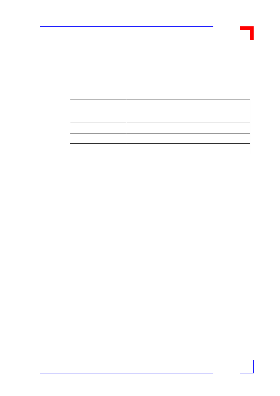
Table 1-2: Abbreviations
AB#
Address Block number (used in some tables in this
manual to signify a 256 byte wide address block cho-
sen out of a maximum permissible 32 addresses)
PBx
Piggyback (where x is the location "A" or "B")
PCB
Printed Circuit Board
PSU
Power Supply Unit