Vmod-2/vmod-2d, Product overview, 8 functional block diagram of the vmod-2 – Kontron VMOD-2D User Manual
Page 20: Figure 1-3: functional block diagram, Way external interface(s)
VMOD-2/VMOD-2D
12/15/97
Product Overview
Page 1 - 10
Man. ID 03139, Rev. Index 0200
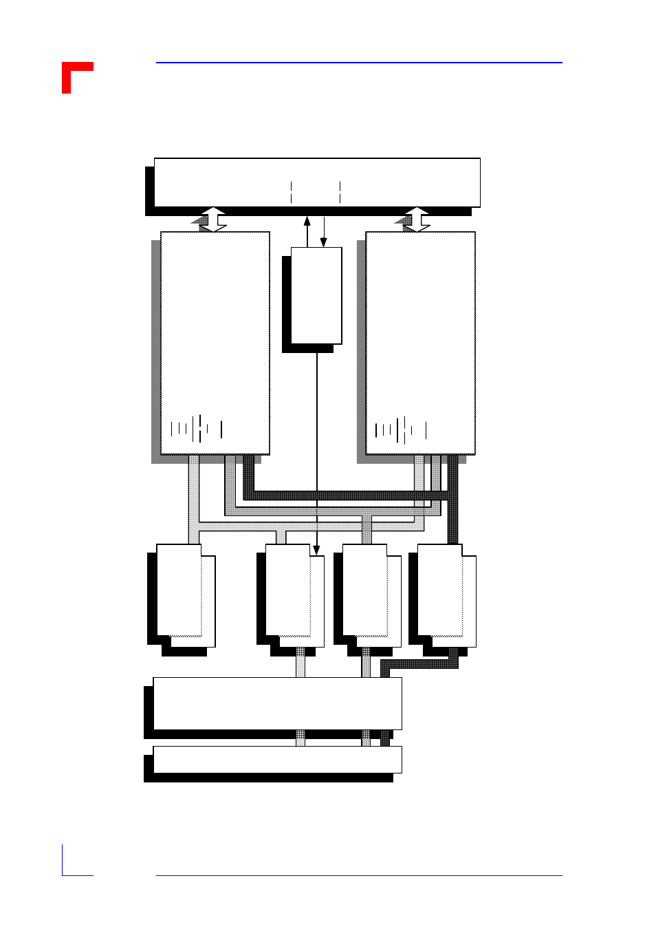
1.8 Functional Block Diagram of the VMOD-2
Figure 1-3: Functional Block Diagram
Da
ta
L
a
tc
h
Da
ta
D
ri
ver
P
ig
g
y
b
a
c
k S
e
lect
A
d
d
re
ss
D
e
c
odi
ng a
n
d
I/O
C
o
n
tr
o
l
L
ogi
c
Ex
te
rn
a
l R
e
s
e
t
In
put
Log
ic
&
Di
sa
b
le
J
u
m
p
e
r
L
o
c
a
l Re
s
e
t
In
te
rr
u
p
t C
o
n
tro
l
Log
ic
a
n
d
IR
Q
* D
riv
e
r
VM
E
b
u
s
L
o
c
a
l/P
B
Co
n
tr
o
l
L
ogi
c
P
iggy
b
a
c
k
"
A
"
(U
pp
e
r Lo
c
a
ti
o
n
)
ID
0.
..15
P
B
I
.D
. dat
a
IA
1.
..11
R
E
SET
CL
K
IA
S
ID
S
0
/ ID
S
1
UD
T
A
CK
0
CS
0
IN
T
0
IN
T
A
0
Us
e
r
I/
O
Ac
c
o
rd
in
g
To
P
ig
g
yb
a
c
k
Ty
p
e
F
itte
d
O
p
ti
o
n
a
l E
x
tr
a
M
u
s
t be
or
d
e
re
d
a
n
d
f
itte
d
P
iggy
b
a
c
k
"
B
"
(L
o
w
e
r L
o
ca
tio
n
)
ID
0.
..15
P
B
I
.D
. dat
a
IA
1.
..11
R
E
SET
CL
K
IA
S
ID
S
0
/ ID
S
1
UD
T
A
CK
1
CS
1
IN
T
1
IN
T
A
1
Us
e
r
I/
O
Ac
c
o
rd
in
g
To
P
ig
g
yb
a
c
k
Ty
p
e
F
itte
d
O
p
ti
o
n
a
l E
x
tr
a
M
u
s
t be
or
d
e
re
d
a
n
d
f
itte
d
Da
ta
A
d
d
re
ss
Co
n
tr
o
l
In
c
lud
in
g.
..
SYSC
L
K
*
SYSR
ES
E
T*
WR
IT
E*
AS
*
DS
0*
DS
1*
IR
Q
1*.
..7
*
IA
C
K
IN
*
IA
C
K
O
U
T*
AM
0
...
5
LW
O
R
D
*
IA
C
K
*
96-way VMEbus Interface Conne ctor
50-way External Interface(s)
Pins 27...50 for Upper Piggyback
Pins 01...24 for Low er Piggyback
Pins
25 & 26
Da
ta
A
d
d
re
ss
Co
n
tr
o
l
A2
4
/A1
6
:D
1
6
/D8
Sl
a
v
e
VM
E
b
u
s
In
te
rf
a
c
e