Elecraft KRX3 User Manual
Page 51
A-4
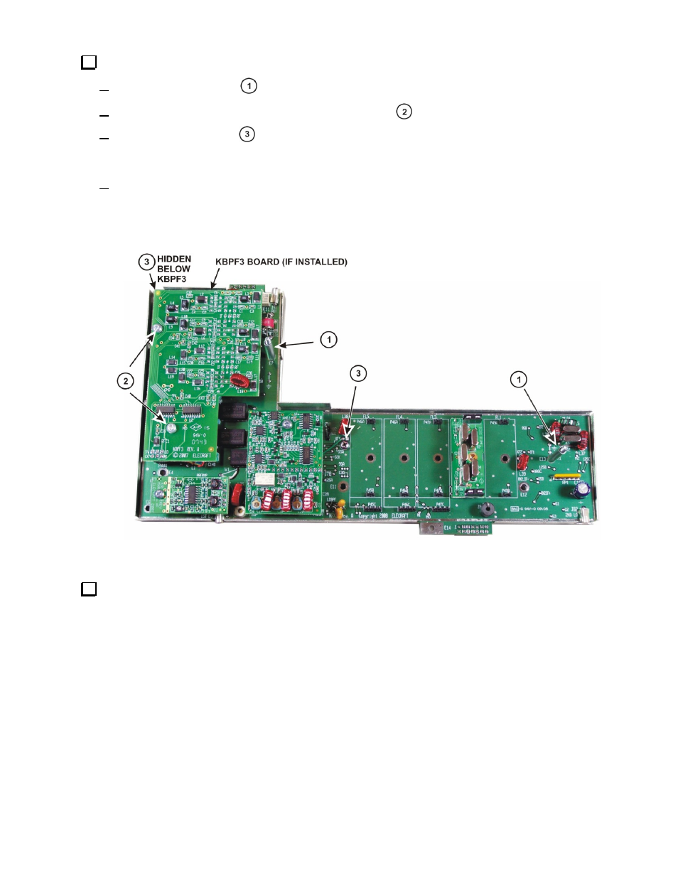
Remove the RF board from the lower half of the enclosure as follows (see Figure A-5):
Remove the two sleeves
from the long screws.
If the KBPF3 option is installed, remove the two screws
and unplug it from the RF board underneath.
Remove the two screws
securing the KRX3 RF board to the bottom half of the enclosure. These
screws thread into bushings attached to the enclosure with screws. If a screw seems to turn without
loosening, hold the corresponding screw on the bottom of the enclosure so it cannot turn.
Lift the RF board out of the enclosure. It is a tight fit. There may be small bumps along the sides of the
board that snap into holes in the sides of the enclosure. Start by lifting carefully at the two extensions
where the board extends outside of the shield while pressing down on the edge of the shield to free it then
work the board up and off of the long screws.
Figure A-5. Removing the RF Board from the Enclosure.
The crystal I.F. filters are installed at positions FL1 thorough FL5 on the RF board. If the KRX3 has been in
use there will be at least one filter already installed. Plan where you are going to install, replace or move the
filters. They must be installed in a certain order according to the following rules:
a) The widest bandwidth filter must be closest to FL1. Note that FL1 is at the right hand end of the row of
filters when the board is arranged to read the silk screening on the pc board. The filters must be in order
of decreasing bandwidth from the right (nearest FL1) to the left (nearest FL5). If you’re installing the K-
FL3B FM filter, place it in position FL1 since it is the widest bandwidth filter available.
b) You may leave unoccupied filter positions as long as the order in a) above is followed. This is handy if
you plan to add more filters later. Note that only a single filter is installed on the board shown in Figure
A-5, leaving space for a wider bandwidth filter to be added in FL1 position and narrower filters to be
added to FL3 through FL5 later if desired. More information and examples for planning your filters is
included in Appendix A of your K3 Owner’s manual.