Elecraft KRX3 User Manual
Page 21
21
Checking and Modifying Resistor R91 and DAC Input Circuits
The value of resistor R91 must be 22 ohms. Perform the following procedure to check the value of the resistor
and, if needed, reduce its value by adding a 27 ohm resistor in parallel with it. Two traces must be cut to ensure
the Digital to Analog Converters (DACs) receive the proper signal levels.
Turn the K3 upside down. Place it on a clean, soft surface to avoid scratching the case.
If the forward section of the bottom cover is not already off, remove it as shown in Figure 8 on page 13.
Locate R91. It is a small surface-mount resistor near the front center of the RF board (see Figure 22).
Use your DMM to measure the resistance across R91 in the circuit. If the resistance is about 22 ohms, you
do not need to add the leaded resistor. Go directly to the next step below. If the resistance is near 100 ohms,
install the 27 ohm (red-violet-black) 1/8-watt resistor as shown in Figure 22. The pads shown were chosen to
make installation easier than trying to solder directly to both ends of R91. Take care not to use more heat or
solder than necessary to avoid damaging the board or forming solder bridges across R91 or to other pads.
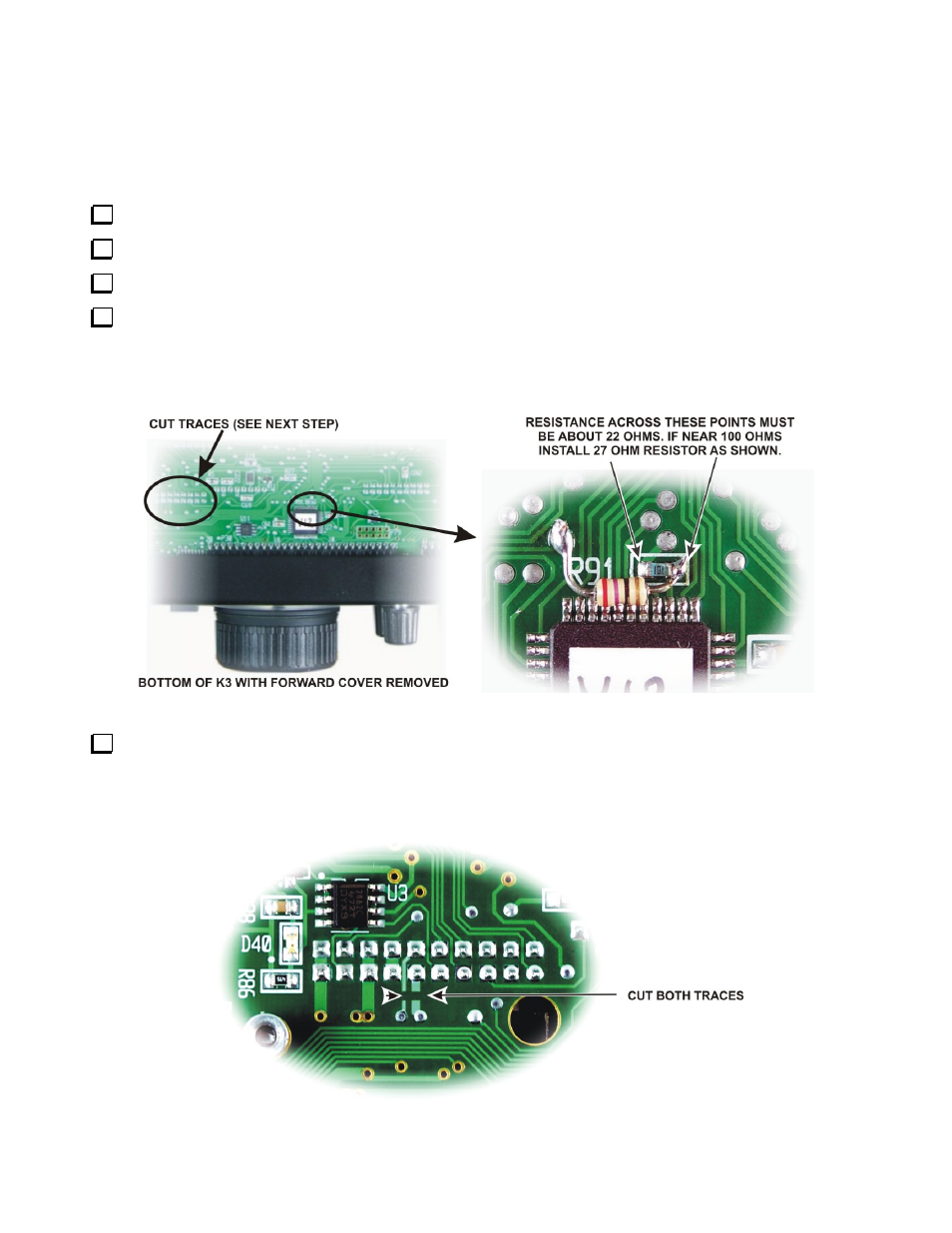
Figure 22. R91 Modification.
Check to see if the traces shown below have been cut. They are on the bottom of the RF board in the area to
the left of R91 with the front panel facing toward you (see Figure 22, above). If not, cut them as shown. This
modification ensures the digital-to-analog converters (DACs) always receive the proper signal levels. It has been
incorporated into all later K3s. Confirm the traces are cut using your DMM. It should indicate an open circuit,
just as if your meter leads were not connected to anything.
Figure 23. Cut Traces.