Elecraft KRX3 User Manual
Page 32
32
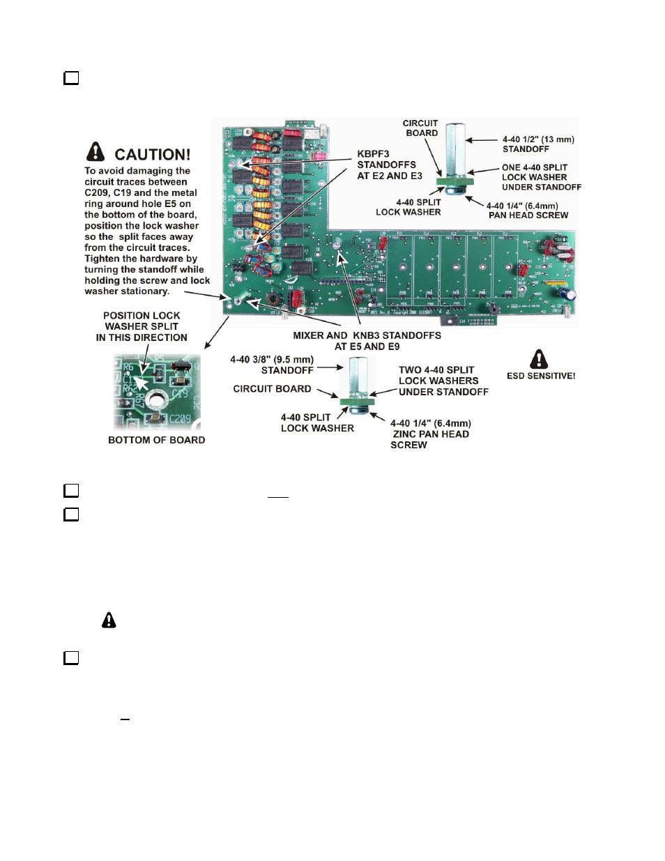
Install four standoffs on the KRX3 main circuit board as shown in Figure 37. Be careful to use the correct
length standoff and the exact combination of washers shown in each location, and carefully follow the
instructions for installing the standoff at E5 to avoid damaging the board.
Figure 37. Installing Standoffs on the KRX3 Main PC Board.
Check to ensure that you installed all four standoffs exactly as shown in Figure 37 above.
Locate the crystal I.F. filters. Two types of filters are available: standard 5-pole filters and optional 8-pole
filters (see Figure 38). One standard 5-pole 2.7 kHz filter is supplied. If you have elected to equip your K3 with
the optional 8-pole 2.8 kHz filter, it has been supplied instead of the 2.7 kHz filter. If you have purchased
additional filters, they may be installed now as well. If you plan to add filters later, spaces may be left for them.
For example, if you plan to add the FM or a 6 kHz AM filter later, you can leave spaces FL1 and FL2 open for
them and install the 2.8 kHz filter in position FL3. The filters are not hard to move about later, so if you aren’t
sure, install the widest at FL1, the next widest at FL2 and so on.
You can add or change filters at any time. A complete, detailed procedure for doing so
after you assemble your K3 is included in Appendix A of this manual.
Enter the following data on Table 1. You will need this information to set up your filters after assembling
your K3. Be sure you’re following the rule described in the step above about the proper order for the filters.
Note that Table 1 is set up with FL1 to the right and FL5 to the left, just as they must be installed on the RF
board.
Enter the bandwidth of each filter in the row below the filter position in which it will be
installed.
(Continued on next page.)