Elecraft KRX3 User Manual
Page 50
A-3
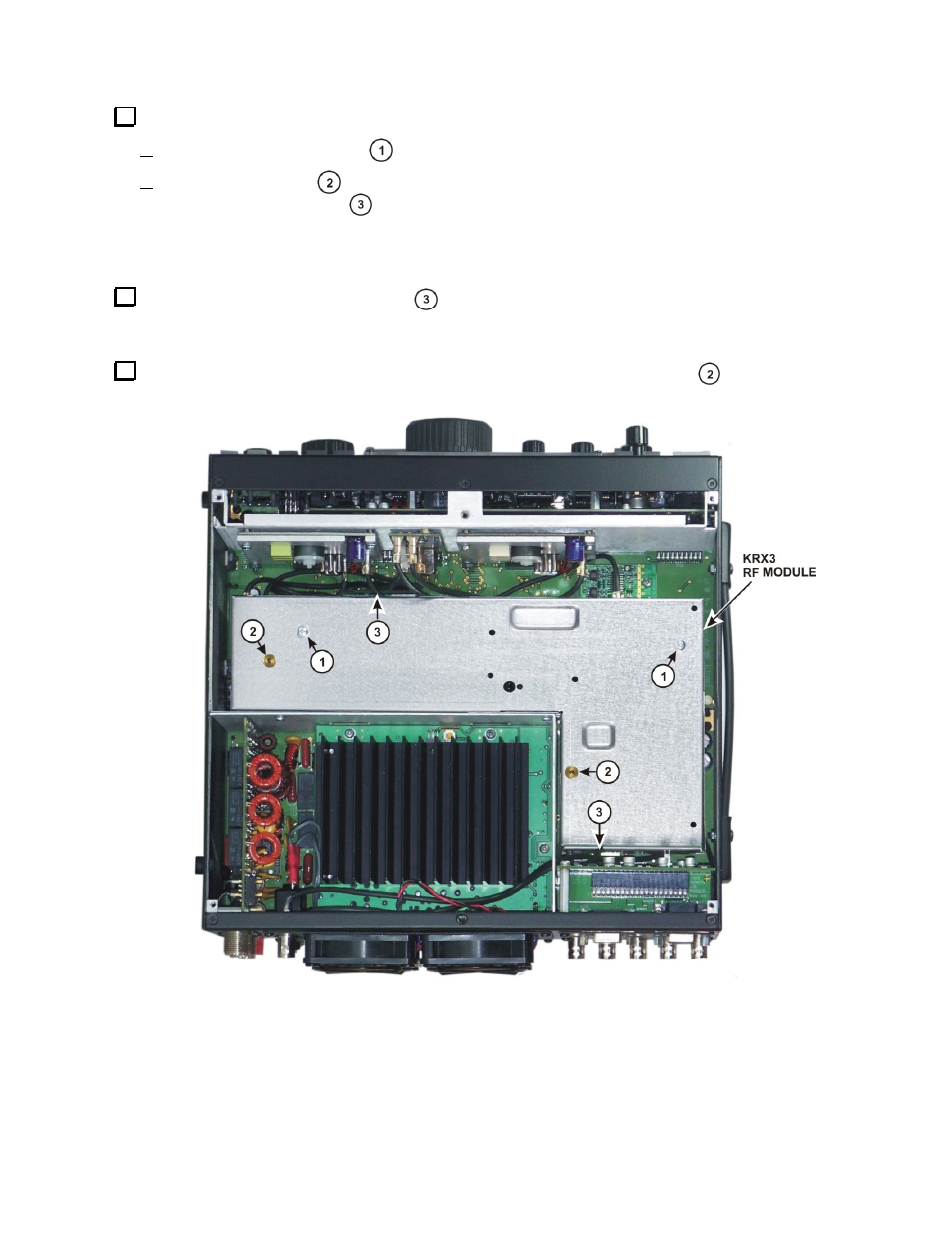
Remove the KRX3 RF module as follows. The circled numbers refer to Figure A-4 below.
Remove the two long screws
that attach the KRX3 enclosure to the K3 main board.
Grip the knurled nuts
and lift the KRX3 enclosure up and out of the K3. The enclosure will unplug
from two interface boards
, one near the front and the other at the back. Also there will be two coaxial
cables attached to the forward edge and usually one cable attached at the back of the enclosure. Carefully
unplug these cables holding onto the metal finger grip, not the black coax. The connectors are held by
friction and slide apart. They do not unscrew.
Remove the two small interface boards
that plug into the board on the bottom of the K3 and the KRX3
enclosure. The boards may still be attached to the K3 main board or may be attached to the connectors on the
KRX3 RF module. Set them aside in an ESD-safe place.
Place the KRX3 RF enclosure on your work table. Remove the two knurled nuts
and lift the top half of
the KRX3 RF enclosure off of the lower half
Figure A-4. Removing the KRX3 RF Module.