Assembling the krx3 subreceiver module – Elecraft KRX3 User Manual
Page 31
31
Replace the 4-40, 3/16” (4.8 mm) black flat head screw that secures the back panel to the 2D fastener as
shown in Figure 31.
Replace the two 4-40 3/8” (9.6 mm) black flat head screws, lock washers and nuts to secure the heat sinks
of U13 and U12 to the side panel as shown in Figure 30.
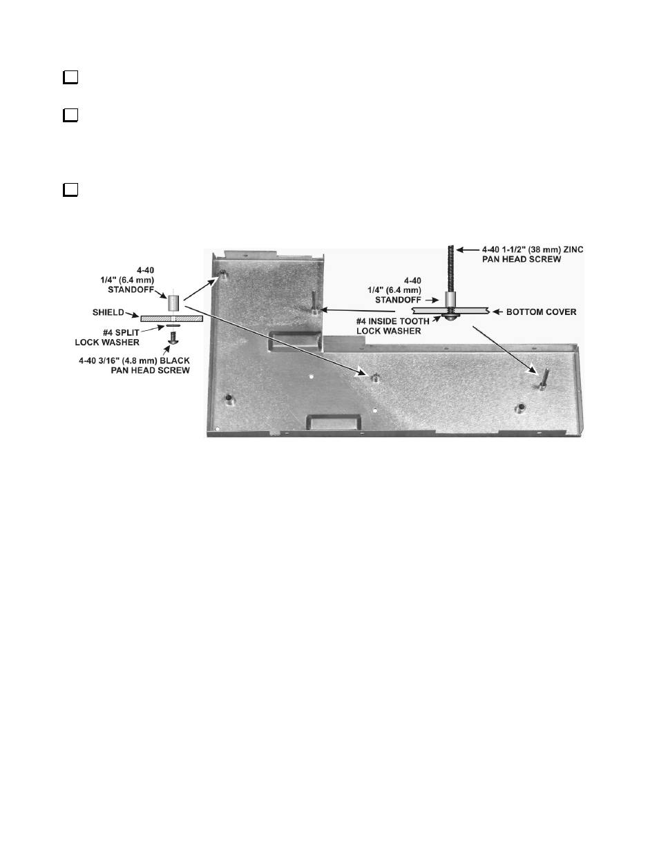
Assembling the KRX3 Subreceiver Module
Install four standoffs on the bottom half of the KRX3 shield assembly as shown in Figure 36. The bottom of
the shield has the shorter permanently mounted standoffs. The standoffs you install go on the same side of the
shield as the permanent standoffs. There are extra holes in the shield. Be sure you put the standoffs in the correct
locations and that the standoffs with the long screws are in the positions shown.
Figure 36. Mounting Standoffs on Shield Bottom.
- KX3 Owner's Manual (58 pages)
- KX3 Assembly Manual (47 pages)
- KX3 Assembly Manual Errata (5 pages)
- KX3-2M (30 pages)
- KX3-PCKT (2 pages)
- KX3 Mobile Installation And Operation Guide (17 pages)
- KX3 Guide for Blind Operators (7 pages)
- KX3 Quick Reference (2 pages)
- K3 Programmers Reference (26 pages)
- KX3 Speaker Grille Instructions (9 pages)
- KXFL3 Filter Option (12 pages)
- KXFL3 Filter Option Errata (2 pages)
- KXAT3 (5 pages)
- KXBC3 (13 pages)
- KXPD3 (4 pages)
- Proset Boom Headset (1 page)
- PX3 Owner's Manual (53 pages)
- PX3 Owners Manual Errata (2 pages)
- KXPA100 Manual (55 pages)
- KXPA100 Assembly Manual (27 pages)
- KXPA100 Assembly Errata (1 page)
- KXPA100 Programmers Reference (24 pages)
- KXAT100 Installation Manual (17 pages)
- KX1 Manual (96 pages)
- KXAT1 (12 pages)
- KXPD1 (7 pages)
- KXB30 (8 pages)
- KXB3080 (20 pages)
- K1 (91 pages)
- K1 1.09 F/W (1 page)
- KNB1 Manual (8 pages)
- KAT1 Manual (15 pages)
- KFL1-2 (2 pages)
- KTS1 (1 page)
- KBT1 Manual (8 pages)
- KBT1 Manual Errata (2 pages)
- K1BKLTKT LCD Mod Kit (6 pages)
- K2 Owner's Manual (171 pages)
- K2 Owner's Manual Errata (1 page)
- K2 PLL (4 pages)
- K2ATOBKIT (15 pages)
- K2ATOBKT (2 pages)
- K2 Keying Modification Instructions (4 pages)
- KPA100 Manual (74 pages)
- KPA100 Shield Upgrade (3 pages)