Elecraft KRX3 User Manual
Page 41
41
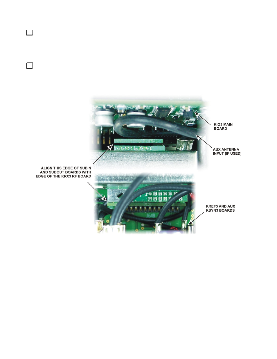
If installed, attach the antenna cable connected to either the KAT3 or to the AUX RF BNC jack on the rear
panel to J92 at the end of the KRX3 as shown. This connector is angled upwards to provide clearance between
the connector and the KIO3 board when the unit is installed. Be certain the TMP connector is fully inserted in
J92. When the KRX3 module is installed the clearance between the connector and the nearby KIO3 board is
very small.
With all the TMP cables attached, lower the KRX3 module into the K3 so that the connectors on the KRX3
mate with the connectors on the SUBIN and SUBOUT interface boards (see Figure 50). The knurled nuts are
provided as handles to make holding the assembly easier. You may need to adjust the cables near the SUBOUT
board so they don’t interfere with mating the connectors. If the connection between J92 and the KAT3 is used,
form the excess cable into a loop in front of the KIO3 board.
Figure 50. Aligning the SUBIN and SUBOUT Connectors.
- KX3 Owner's Manual (58 pages)
- KX3 Assembly Manual (47 pages)
- KX3 Assembly Manual Errata (5 pages)
- KX3-2M (30 pages)
- KX3-PCKT (2 pages)
- KX3 Mobile Installation And Operation Guide (17 pages)
- KX3 Guide for Blind Operators (7 pages)
- KX3 Quick Reference (2 pages)
- K3 Programmers Reference (26 pages)
- KX3 Speaker Grille Instructions (9 pages)
- KXFL3 Filter Option (12 pages)
- KXFL3 Filter Option Errata (2 pages)
- KXAT3 (5 pages)
- KXBC3 (13 pages)
- KXPD3 (4 pages)
- Proset Boom Headset (1 page)
- PX3 Owner's Manual (53 pages)
- PX3 Owners Manual Errata (2 pages)
- KXPA100 Manual (55 pages)
- KXPA100 Assembly Manual (27 pages)
- KXPA100 Assembly Errata (1 page)
- KXPA100 Programmers Reference (24 pages)
- KXAT100 Installation Manual (17 pages)
- KX1 Manual (96 pages)
- KXAT1 (12 pages)
- KXPD1 (7 pages)
- KXB30 (8 pages)
- KXB3080 (20 pages)
- K1 (91 pages)
- K1 1.09 F/W (1 page)
- KNB1 Manual (8 pages)
- KAT1 Manual (15 pages)
- KFL1-2 (2 pages)
- KTS1 (1 page)
- KBT1 Manual (8 pages)
- KBT1 Manual Errata (2 pages)
- K1BKLTKT LCD Mod Kit (6 pages)
- K2 Owner's Manual (171 pages)
- K2 Owner's Manual Errata (1 page)
- K2 PLL (4 pages)
- K2ATOBKIT (15 pages)
- K2ATOBKT (2 pages)
- K2 Keying Modification Instructions (4 pages)
- KPA100 Manual (74 pages)
- KPA100 Shield Upgrade (3 pages)